

Advancing modular microfluidics: Stereolithographic 3D printing of reconfigurable connectors for bioanalytical applications

Traditional monolithic microfluidic devices are constrained by their inability to accommodate modifications to circuit elements, necessitating complete redesign and refabrication. To address these limitations, this study introduces modular microfluidic connectors fabricated via stereolithographic (SL) 3D printing. We designed and evaluated three distinct connector types—tessellated, sponge, and solid-walled—using tailored photoresins to enhance reusability, flexibility, and sealing performance. The tessellated connectors, printed with poly(ethylene glycol) diacrylate (PEGDA; Mw ~258) and incorporating an octet unit cell structure, reduced the rigidity of PEGDA prints, improving reusability under moderate conditions. The sponge connectors, fabricated from a PEGDA and 2-hydroxyethyl acrylate (2-HEA; Mw ~116) blend (2-HEA-co-PEGDA), exhibited greater flexibility; however, swelling in aqueous environments may limit their long-term utility. In contrast, the solid-walled connectors, produced with commercial Asiga Soft Resin, demonstrated superior reliability and adaptability, as validated in a reconfigurable concentration gradient generator with scalable output capabilities. Cytocompatibility tests confirmed that PEGDA-printed devices, following isopropanol and ultraviolet post-processing, are suitable for bioanalytical applications that do not require incubation. These findings establish SL 3D printing as a promising method for developing flexible, reconfigurable microfluidic platforms, with potential uses in material synthesis, chemical analysis, and point-of-care diagnostics. While challenges related to environmental durability persist, these advances lay the foundations for developing more robust and adaptable microfluidic systems with versatile applications.
1. Introduction
Over the past few decades, microfluidic technology has gained significant attention and achieved substantial advancement across various fields, including biomedical research, chemical analysis, point-of-care testing, and material synthesis. Microfluidics enables precise fluid control at the microscale, leading to reduced reagent consumption and enhanced experimental efficiency.1–3 However, despite its advantages, the widespread adoption and further development of microfluidic systems face considerable challenges. One major limitation stems from the prevalent design of microfluidic devices, in which all functional elements are integrated into a single chip. Monolithic microfluidic devices lack the flexibility to adapt to dynamic application scenarios because each chip is typically designed for a specific purpose. Additionally, as device structures become more complex, designing and fabricating these systems require specialized skills and expertise. The increasing number of functional units in each device also demands larger surface areas for micromachining, escalating manufacturing costs, and difficulty. A flexible, reconfigurable, and standardized microfluidic platform could address these challenges by simplifying the design and fabrication processes, thereby advancing microfluidic technology.4
To overcome these limitations, the concept of modular microfluidics has emerged. This approach involves the integration of discrete, interchangeable microfluidic modules that can be assembled and reconfigured as needed. Each module is designed, tested, and fabricated independently, improving system design efficiency and construction flexibility.5–7 For example, in a monolithic microfluidic chip, modifying a single functional part often requires redesigning and retesting the entire chip. In contrast, a modular system allows users to replace only the faulty module without needing to fabricate the entire system again, reducing manufacturing costs and easing maintenance. Moreover, modularity enhances adaptability, allowing users to quickly adapt and optimize microfluidic systems for specific applications, hence fostering innovation and expanding the scope of microfluidic technology. For instance, in point-of-care testing, where real-time adjustments to system configurations are often difficult to achieve in monolithic systems, this adaptability is particularly valuable. As a result, modular microfluidics offers a more practical, versatile, and field-deployable approach for a wide range of applications.8–13
Modular microfluidic systems consist of discrete functional modules, many of which incorporate complex 3D geometries to facilitate assembly. However, traditional manufacturing techniques, such as dry/wet etching and polydimethylsiloxane (PDMS) micromolding, are not well-suited for fabricating highly intricate chips. Consequently, digital manufacturing technologies provide an alternative approach for producing complex structures. Assisted by computer-aided design (CAD) and control, digital manufacturing facilitates a range of tasks, including 3D modeling, performance simulation, automated fabrication, rapid prototyping, and quality control. These technologies can be broadly categorized into additive manufacturing (also known as 3D printing) and subtractive manufacturing, each with distinct advantages and limitations that should be thoroughly considered before adoption.14
In recent years, 3D printing has gained significant traction for microfluidic fabrication due to its advantages in rapid design iteration, geometrical freedom, and low-cost prototyping. In addition to these performance advantages, fabrication cost is also an important consideration. Traditional microfabrication methods, such as soft lithography and micromilling, typically involve cleanroom facilities, photomasks, and manual bonding steps, leading to higher infrastructure and labor costs. In contrast, 3D printing enables rapid, one-step production of enclosed structures without post-alignment or additional sealing processes. Recent studies have demonstrated that additive manufacturing significantly reduces both fabrication time and labor requirements, resulting in lower overall device costs compared to traditional microfabrication.15 Based on our experience, the turnaround time from design to prototype can be less than 1 h, making 3D printing particularly attractive for low-volume production, iterative development, and rapid prototyping of customized microfluidic devices.
Common 3D printing techniques include fused deposition modeling (FDM), multi-jet modeling (MJM), and stereolithography (SL). However, not all 3D printing techniques are equally suited for microscale feature production. FDM provides a low-cost platform and compatibility with various thermoplastics such as polylactic acid (PLA) and acrylonitrile butadiene styrene (ABS)”, making it attractive for general-purpose device fabrication. However, its relatively coarse resolution, limited by nozzle diameter and thermal control, often results in rough surfaces and difficulty in forming narrow or unsupported channels. As a result, FDM-printed microfluidic devices are typically constrained to millimeter-scale features with limited design flexibility. MJM offers improved resolution and multi-material printing capabilities, enabling the use of elastomers and rigid plastics through ultraviolet (UV)-curable photopolymers and sacrificial support gels. However, the removal of support material is diffusion-limited and often incomplete for channels smaller than 750 μm. In addition, the proprietary nature of MJM resins restricts modifications to improve biocompatibility or mechanical properties, limiting their adaptability for biological applications. Among these technologies, SL has emerged as a promising technique for printing functional microfluidic devices. SL uses patterned light to initiate photopolymerization in liquid resin, allowing the formation of highly detailed structures and smooth surfaces. The in-plane (xy) resolution is defined by the projector’s pixel size, while the layer height (z-resolution) can be finely tuned by adjusting printing parameters and resin viscosity. Notably, SL enables the fabrication of embedded channels and self-supporting geometries without the need for post-print bonding or sacrificial removal. This capability is particularly important for microfluidic applications where internal channel fidelity and sealing reliability are critical. Moreover, SL supports the use of custom resin formulations, which allows users to create materials with the required properties. These combined advantages—precision, geometric freedom, material versatility, and smooth surface quality—make SL the ideal choice for our modular microfluidics system.16–19
While several studies have reported Lego-inspired modular microfluidic systems, these approaches often require post-processing or additional components to achieve fluidic interconnection. For example, Ong et al.20 proposed a modular system by integrating self-aligning magnetic interconnects into replica-molded microfluidic units, enabling easy alignment but requiring separate fabrication steps for magnet embedding. Similarly, Owen et al.21 utilized micromilling to create channels on commercial Lego bricks. To seal the channels, a multilayer strategy was employed, where a polyethylene film was bonded with acrylic adhesive and reinforced with cyanoacrylate along the edges. On the other hand, although some studies have used 3D printing to fabricate modular microfluidic systems that do not require postprocessing to achieve fluid sealing and interconnection, several general limitations remain. Most of these systems are printed using commercial resins, which are difficult to modify to meet specific application requirements. In biomicrofluidic applications in particular, biocompatibility and optical transparency are often essential, yet frequently lacking in commercial materials. Additionally, many of these 3D-printed systems rely on direct coaxial nesting or interference fits for sealing, which limits reusability and reduces mechanical flexibility. Hence, these examples highlight the complexity of achieving reliable fluidic sealing in prior modular platforms.6,8,11,12,16,22,23
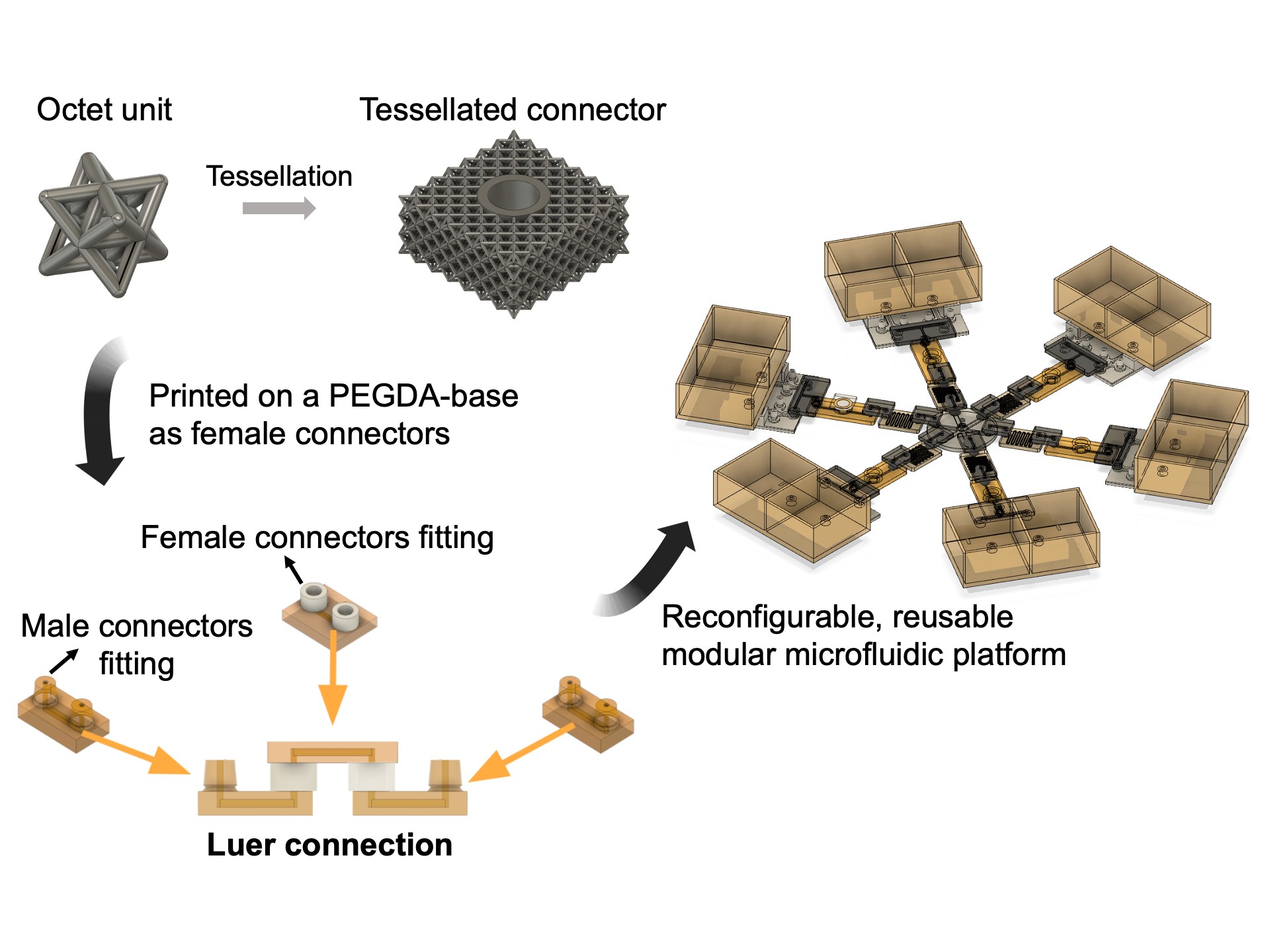
In this study, we developed and evaluated three types of modular microfluidic connectors based on the Luer connection system, which employs male and matching female connectors to enable a “plug-and-play” approach for easy reconfiguration of microfluidic platforms. The fully 3D-printed connector system enables press-fit sealing and easy reconfiguration without the need for adhesives, magnets, or external fasteners. We selected SL 3D printing as the fabrication method, using our self-formulated photoresins as materials. Initially, poly(ethylene glycol) diacrylate (PEGDA; Mw ~258) resin was used to fabricate both male and female connectors due to its high resolution and optical transparency.24 However, PEGDA’s rigidity led to low reusability and reliability of connectors, as abrasion occurred between the male and female components during the connecting process when the female connector had a solid-walled structure. To address this issue, we incorporated a tessellated structure into the female connector’s wall using a stretching-dominant unit cell, called the octet unit, which physically alleviates the rigidity of PEGDA.25 This structure effectively distributes applied pressure through slight beam deformations, significantly enhancing the reusability and mechanical reliability of the female connector compared to the solid-walled version. Additionally, we developed a second connector type with a similar structure design but with a new resin formulation—a blend of 2-hydroxyethyl acrylate (2-HEA) and PEGDA monomers, termed 2-HEA-co-PEGDA. This resin exhibits gel-like properties, offering greater flexibility than pure PEGDA. Our objective was to compare the performance between female connectors made of solid and soft resins (PEGDA and 2-HEA-co-PEGDA). Furthermore, we tested a commercially available resin, Asiga Soft Resin, to evaluate its performance and durability. Results indicated that all three connector types demonstrated high reliability at room temperature. As a proof of concept, we proposed a modular drug screening platform as an application of our 3D-printed connectors. However, during experiments, mechanical failures were observed when the connectors were exposed to warm cell culture medium and incubator conditions, indicating a limitation for longterm cell culture applications, such as organ-on-chip (OoC) systems. Despite these challenges, our connectors remain highly functional for other modular microfluidic applications. We also highlight that this study serves as a caution for researchers considering PEGDA as a material for fabricating devices intended for long-term cell culture.
2. Materials and methods
2.1. Materials
PEGDA (Mw ~258) and 2-HEA (Mw ~116) were purchased from Sigma-Aldrich (United States of America [USA]). Poly(ethylene glycol) methyl ether methacrylate (PEGMEMA) was also obtained from Sigma-Aldrich (USA). Asiga Soft Resin was sourced from Asiga (Australia). Phenylbis(2,4,6-trimethylbenzoyl) phosphine oxide (OM819; formerly Irgacure-819) was purchased from BASF (Germany), while 2-isopropylthioxanthone (ITX) was obtained from PL Industries (USA). Sylgard 184 PDMS prepolymer and curing agent were purchased from Dow Corning (USA). 3-(Trimethoxysilyl)propyl methacrylate (TMSPMA) and Pluronic (F127) were obtained from Sigma-Aldrich (USA). The MDA-MB-231 breast cancer cell line (BCRC 60425) was obtained from the Bioresource Collection and Research Center (BCRC), Food Industry Research and Development Institute (Taiwan). High-glucose Dulbecco’s Modified Eagle Medium (HG-DMEM), live/dead staining solution (Calcein green and ethidium homodimer) were purchased from Thermo Fisher Scientific Inc. (USA). Fetal bovine serum (FBS) and penicillin–streptomycin solution were sourced from HyClone, Cytiva (USA). Phosphate-buffered saline (PBS) was obtained from Sigma-Aldrich (USA).
2.2. Preparation of photopolymers
The selection of photoinitiator and photoabsorber depends on the solvent polarity of the resin or hydrogel precursor. In this study, the PEGDA-258 monomer serves as the primary component in all proposed resin formulations. Due to its non-polar nature, we used OM819 as the photoinitiator and ITX as the photoabsorber. To prepare the PEGDA-258 resin, we mixed 0.6 wt% OM819 and 0.6 wt% ITX with the PEGDA-258 monomer. For the 2-HEA-co-PEGDA resin, PEGDA-258 and 2-HEA were each first mixed separately with 0.6 wt% OM819 and 0.6 wt% ITX. The two monomer solutions were then combined in a 15:85 volumetric ratio of PEGDA to 2-HEA to form the final solution.
2.3. 3D printing process
All objects were designed using Autodesk Fusion 360 (Autodesk Inc., USA). The designs were exported in STL format and then sliced using Asiga Composer (Asiga, Australia), with specified layer thicknesses. Printing parameters, including light intensity, exposure time (Figure S1), and separation distance (Figure S2), were controlled within this software. Detailed parameter setting tests are provided in the Supplementary file, including the XY resolution test (Figure S3) and the Z-resolution test (Figure S4). The final printing file was then uploaded to a digital light projection-based SLA 3D printer (Asiga PICO 2 HD, Asiga, Australia). This printer features a 385 nm UV-LED light source with an X–Y pixel resolution of 27 μm.
To ensure a smooth print surface, a glass slide was attached to the printer’s build platform. Before attachment, the glass slide was rinsed sequentially with acetone, isopropanol (IPA), and deionized (DI) water, followed by drying in an 80°С oven for 20 min. The slide was then silanized overnight using TMSPMA to ensure stable adhesion of the photopolymerized resin to the glass slide surface. More details on this procedure can be found in our previously published protocol.24 The glass slide was finally attached to the build platform using a drop of PEGDA resin, which was exposed to ambient light for 5 min to secure it in place.
After printing, the object was carefully removed from the glass slide by wedging a razor blade between the print and the surface. The printed object then underwent postprocessing to remove unreacted monomers or additives. First, the printed object was immersed in an IPA bath for approximately 30 min, avoiding exposure to ambient light. Next, the object was rinsed with fresh IPA and DI water (and subsequently flushed if it contained channels) to ensure complete removal of residual unreacted resins. Finally, after air drying, the print was exposed to UV light for 2 min to ensure full resin curing and enhanced structural integrity. To assess whether post-processing affects dimensional accuracy, we measured the printed parts (3 × 3 × 3 mm blocks) before and after UV postcuring and observed a shrinkage of approximately 2–5%. This dimensional change is primarily attributed to further polymerization during post-curing. Nevertheless, we noted that this level of shrinkage did not compromise the functionality or sealing performance of our devices.
2.4. Design of connectors
In this study, we compared three different connector designs, all based on the Luer connection system. The Luer connection employs male and female connectors, facilitating a straightforward “plug-and-play” approach that enables users to easily configure modular microfluidic systems. As illustrated in Figure 1, male or female connectors were integrated directly into the microfluidic chips during printing. Modules featuring female connectors serve as bridges, linking functional modules equipped with male connectors. The bottom parts of all modules, which contain channel structures, were printed using PEGDA resin due to its high resolution and excellent printability. We designed and tested three distinct connector types: tessellated connector, sponge connector, and solid-walled connector. Each type featured a unique structural design for the female connector and was printed using different resins, whereas the male connector design remained unchanged across all types.

Figure 1. Schematic of the connection method using Luer connectors for modular microfluidics. The figure illustrates the Luer connection system employed in the modular microfluidic setup. Male connectors (left and right) are designed to fit into corresponding female connectors (top), enabling a secure “plug-and-play” assembly. This configuration allows for easy and flexible connection of microfluidic modules, ensuring a reliable and customizable platform. The corresponding structure (bottom) features an example of how the connectors can bridge two separate microfluidic modules, facilitating fluidic communication between them.
2.4.1. Tessellated connector design
Our primary objective in designing the connectors was to ensure both reliability and reusability. To achieve these properties, the female connector needed to be flexible enough to deform and adapt to the shape of the male connector. Despite PEGDA exhibiting excellent printability, its mechanical properties—characterized by a Young’s modulus of approximately 870 MPa and low elastic strain—make it unsuitable for fabricating female connectors with a purely solid structure. Both PEGDA-printed male and female connectors were prone to abrasion during the connection process, which compromised structural integrity and reduced liquid sealing capacity.
To introduce flexibility, we hypothesized that incorporating bendable microstructures into the female connector could facilitate effective pressure distribution upon male connector insertion. Jiang et al.25 demonstrated that compressive behaviors differ significantly between bending-dominant and stretching-dominant lattices. In a stretching-dominant octet unit cell, the stress response is non-monotonic and exhibits domains with negative stiffness. This phenomenon occurs because compressive loading on the Octet lattice is primarily applied along the beam axes, causing beam buckling once a critical point is reached.25
Based on these findings, we selected the octet unit cell as the repeated structure to tessellate the walls of the female connector (Figure 2A). The tessellated connectors were composed of octet unit cells, arranged in a 5 × 5 × 2.25 mm (length × width × height) block. Each block contained a cylindrical hole at its center, with an inner diameter of 1.7 mm and an outer diameter of 1.9 mm, serving as the connecting site. The beam size of the octet unit cells was 100 μm in diameter and 300 μm in length.

Figure 2. Schematic of the connector designs for modular microfluidics. (A) Tessellated connector design: The octet unit cell (left) was used to create a tessellated structure for the female connector. The tessellated design (right) enhances flexibility and allows for effective pressure distribution during connection. The connector features a cylindrical hole with an inner diameter of 1.7 mm and an outer diameter of 1.9 mm. (B) Sponge connector design: A snowflake-like unit cell (left) was used to generate an “inverted tessellation” (middle), creating voids in the cylinder’s wall that increase the flexibility of the female connector. The sponge connector’s design ensures better adaptability and sealing during connection, with a central tunnel diameter of 1.7 mm (right). (C) Solid-walled connector design: The solid-walled female connector is a straightforward cylindrical structure with a diameter of 5 mm and a height of 2.25 mm. The design leverages the elastomeric properties of the material to provide sufficient flexibility, with a central tunnel diameter of 1.7 mm. (D) Male connector design: The male connectors feature a cylindrical shape with fixed top and bottom diameters of 1.6 mm and a varying middle diameter between 1.65 and 1.8 mm, depending on the type of female connector they are paired with.
2.4.2. Sponge connector design
To further mitigate the hard plastic properties of PEGDA prints, we extended the tessellated connector concept to develop and evaluate a new connector type fabricated using another photoresin formulation, named 2-HEA-co-PEGDA. This resin formulation retains high printing resolution and favorable physical properties of PEGDA while exhibiting gel-like characteristics due to the presence of 2-HEA. Consequently, 2-HEA-co-PEGDA prints demonstrate greater flexibility than PEGDA while maintaining the ability to form finely detailed structures. We hypothesized that female connectors made from 2-HEA-co-PEGDA would offer improved reusability and reliability, as their enhanced flexibility could reduce abrasion during the connection process and provide better sealing performance.
To achieve this, we designed a snowflake-like unit cell to tessellate a cylindrical structure. This structure was then inverted, forming an “inverted tessellation” that generated voids within the cylinder’s wall (Figure 2B). The snowflake-like unit cell consisted of beams measuring 250 μm in diameter and 500 μm in length, while the cylinder itself was designed with a diameter of 5 mm and a height of 5 mm, featuring a 1.7 mm-diameter inner tunnel as the central connecting site. Due to the spongelike cross-sectional appearance of this female connector design, we named it the sponge connector. The bottom parts of the sponge connectors were printed using PEGDA resin, and we employed our print–pause–print (PPP) protocol, referred to as “3P-printing,” to fabricate the sponge connectors with 2-HEA-co-PEGDA resin layered on top of the PEGDA base.26
2.4.3. Solid-walled connector design
Finally, we evaluated the Asiga Soft Resin, a commercial photoresin, for the fabrication of female connectors. Asiga Soft Resin prints exhibit elastomeric properties, making them highly deformable yet sufficiently tough to maintain structural integrity. Given these properties, we opted for a simple connector design—a solid-walled cylinder with a diameter of 5 mm and a height of 2.25 mm, featuring a 1.7-mm-diameter connecting tunnel at its center (Figure 2C). The bottom parts of these connectors were printed using PEGDA resin, and the 3P printing protocol was used to layer Asiga Soft Resin onto the PEGDA base to print the female parts. Due to the high viscosity of Asiga Soft Resin, the IPA bath process (Section 2.3) was conducted dynamically to aid in resin dissolution. Additionally, thorough IPA flushing was required to clean the channels and remove any residual resin.
2.4.4. Male connector design
The male connectors used in this study shared a consistent cylindrical geometry, regardless of the female connector type (Figure 2D). The top and bottom diameters were fixed at 1.6 mm, while the middle section diameter varied between 1.65 and 1.8 mm, depending on the specific female connector used. All male connectors, including their bottom parts, were printed using PEGDA resin to ensure high-resolution printing and structural strength.
2.5. Cytocompatibility test
To evaluate the cytocompatibility of PEGDA prints, we cultured malignant breast cancer cells (MDA-MB-231) in HG-DMEM supplemented with 10 vol% FBS and 1% penicillin–streptomycin. Prior to cell culture, the printed devices underwent a post-processing treatment to remove unreacted monomers. The devices were soaked in IPA for 2 h, cured under UV light in a water bath for 12 h, and then placed in a well-sealed Petri dish to dry in a 60 °C oven for 30 min. Following treatment, 5.6 × 10⁴ cells were suspended in 3 mL of HG-DMEM medium and seeded into each printed Petri dish. The dishes were then incubated for 72 h under a 5% CO2 atmosphere at 37 °C and 100% humidity. On the third day, the cells were washed with PBS and stained with Live Cell imaging solution containing 2 μM Calcein green and 1 μM ethidium homodimer for fluorescent imaging of live/dead cells.
2.6. PDMS coating procedure
The PDMS prepolymer (Sylgard 184, Dow Corning, USA) was prepared by mixing it with the curing agent at a 10:1 ratio and then degassed in a vacuum chamber to remove air bubbles. After degassing, uncured PDMS was carefully applied to the device surface with a stick, ensuring that the deposited PDMS reached a predefined mark printed on the Petri dish wall, forming a 100 μm-thick coating layer. Following the coating process, the device was placed in a clean dish with the cover on to cure at room temperature overnight.27,28
2.7. Statistical analysis
All experiments were performed in triplicates using independent samples per condition to ensure reproducibility and statistical reliability. Data are presented as mean ± standard deviation. Data analysis and graph generation were performed using GraphPad Prism (GraphPad Software, USA) and ImageJ (National Institutes of Health, USA) for image processing and quantification.
3. Results and discussion
3.1. Performance evaluation of three connector designs
Reliability and reusability are critical indicators for connectors used in modular microfluidic systems. An effective connector design should enable multiple reuses without experiencing liquid leakage. To assess these characteristics, we conducted bursting pressure tests to measure the maximum pressure each connector could withstand per insertion. For these tests, we constructed a simple device in which a female connector bridge linked two male connector bridges (Figure 3A). A computer-controlled air pressure source was used to drive fluid into the inlet of the assembled device. Once the fluid had flowed through the entire device, the outlet was blocked, and the air pressure was gradually increased until leakage was observed at the connecting sites. The pressure at which leakage occurred was recorded as the bursting pressure, providing a quantitative assessment of connector performance.

Figure 3. Bursting pressure tests for three connector designs. (A) Schematic of the experimental setup used for bursting pressure tests. Fluid was driven into the inlet of the assembled device by a computer-controlled air pressure source. The outlet was blocked, and the air pressure was increased until leakage occurred at the connecting sites, allowing for the measurement of bursting pressure. (B) Bursting pressure test results for PEGDA-printed solidwalled connectors. The performance significantly declined after 2–3 uses, with an initial maximum pressure of 15 psi. The decline was attributed to the rigidity and low flexibility of PEGDA, leading to abrasion and reduced sealing capacity. (C) Bursting pressure test results for tessellated connectors. The octet unit tessellated connectors, particularly those paired with a 1.75 mm male connector, exhibited stable performance across multiple uses. The design provided effective physical support, allowing PEGDA to be used in modular microfluidics. (D) Bursting pressure test results for sponge connectors. The 2-HEA-co-PEGDA resin used for the sponge connectors provided greater flexibility, resulting in more consistent performance and higher reusability than tessellated connectors. However, the connectors exhibited a loss of sealing capacity after prolonged use due to material swelling. (E) Bursting pressure test results for solid-walled connectors made with Asiga Soft Resin. These connectors demonstrated the ability to consistently hold seals up to 25 psi, even after multiple reconnections. n = 5. Abbreviations: 2-HEA-co-PEGDA, 2-hydroxyethyl acrylate-co-poly(ethylene glycol) diacrylate; PEGDA, poly(ethylene glycol) diacrylate.
As previously mentioned, PEGDA-printed structures are highly rigid due to their low elastic strain and high Young’s modulus. These properties were clearly reflected in our tests (Figure 3B). Although initial attempts demonstrated effective sealing, with connectors withstanding pressures up to 15 psi, performance declined significantly after 2–3 uses. This rapid loss of sealing capacity was attributed to PEGDA’s high rigidity and low flexibility, which led to abrasion of both the solid female and male connectors during the connection process. The size of the male connector also played a critical role in sealing performance. The female connecting site diameter was fixed at 1.7 mm, and we observed that the 1.70 mm male connector exhibited the highest initial bursting pressure but was only usable once. The 1.65 mm male connector, while exhibiting a lower bursting pressure, demonstrated better reusability but with gradually decreasing pressure over multiple uses. Conversely, male connectors larger than 1.70 mm in diameter exhibited zero bursting pressure, as they could not be inserted into the female connectors. In contrast, tessellated connectors performed as expected (Figure 3C). The octet unit tessellated connectors, particularly when paired with a 1.75 mm male connector, exhibited a stable performance curve, indicating strong reliability and reusability. The slight decrease in bursting pressure observed over multiple uses was caused by minor abrasion, which gradually created small gaps between the male and female connectors. This trend was consistent across other male connector sizes, except for the 1.80 mm male connector, where excessive deformation caused the female connector to crack. These results confirmed that our tessellated connector design could effectively provide structural support, enabling the use of hard plastics like PEGDA in modular microfluidic systems.
The sponge connector was fabricated using a photoresin blend—2-HEA-co-PEGDA. 2-HEA is a hydrophilic monomer commonly used in contact lenses due to its flexibility, transparency, and moisture absorption capabilities. Similar to our PEGDA-co-PEGMEMA resin,29 the material properties of 2-HEA-co-PEGDA could be easily tuned by adjusting the composition ratio.29 Following a series of optimization tests, we determined that an 85% 2-HEA-co-PEGDA blend (85:15, 2-HEA:PEGDA) provided the optimal balance of mechanical performance and printability. This formulation exhibited high print resolution and gel-like properties, making it softer than PEGDA. Moreover, unlike most commercial resins that produce soft prints, this formulation had lower viscosity, which facilitated the cleaning and draining of unreacted monomers.
Although 2-HEA-co-PEGDA is inherently soft, a pure solid structure was prone to breaking under pressure. However, the voids within the sponge connector walls allowed for deformation under compressive pressure. Combined with its intrinsic material properties, this design made the sponge connector highly compressible. This flexibility contributed to greater reusability than the tessellated connector, resulting in more consistent bursting pressure test results (Figure 3D). Additionally, the sponge connector could accommodate a wider range of male connector sizes compared to the tessellated connector. However, after a few hours of use, the sponge connector’s sealing ability deteriorated, leading to the disassembly of the connected devices. Swelling tests revealed that the 2-HEA-co-PEGDA material had a swelling rate of up to 17%, which was significantly higher than that of PEGDA resin (~2%). Consequently, despite its superior mechanical properties, this new resin formulation is only suitable for short-term application.
Based on our experience with the 2-HEA-co-PEGDA resin, we hypothesized that the material used for female connectors should be hydrophobic to minimize swelling and enhance moisture resistance, particularly for elastomeric or gel-like resins. Meanwhile, it needed to maintain flexibility and toughness to ensure durability and reusability. To meet these criteria, we selected Asiga Soft Resin, a commercial resin, for testing. According to the manufacturer’s specifications, this resin possesses good elasticity and hydrophobicity, aligning well with our requirements. However, its detailed composition remains proprietary and undisclosed. Due to its inherent toughness and flexibility, we designed the female connector with solid walls, allowing it to deform and maintain sealing pressure without requiring previously introduced structural modifications. While the soft resin exhibited sufficient resolution for microchannel fabrication, the resulting prints appeared blurry, making them less ideal for microfluidic applications. Furthermore, the high viscosity of the soft resin made the draining and cleaning processes difficult. Therefore, the solid-walled connector was fabricated using the 3P-printing protocol, where Asiga Soft Resin was printed onto a PEGDA base. The bursting pressure tests demonstrated that these soft resin female connectors could reliably maintain sealing up to 25 psi, even after multiple reconnections (Figure 3E).
With its ability to maintain sealing under high pressure and deliver consistent performance after multiple uses, the solid-walled connector made from Asiga Soft Resin emerged as a promising design for constructing large-scale modular microfluidic platforms. To further demonstrate its reliability and scalability, we built a modular concentration gradient generator (CGG). CAD models of each module, including the source block, male bridge, mixer, female bridge, and T-connection, are displayed in Figure 4A. In the CGG operating setup (Figure 4B), two source blocks served as the inlet ports to introduce dyed streams into the fluidic circuit, where they were mixed by mixers and split by T-connections. These results underscore the excellent sealing capacity of the solid-walled female connectors, which can be attributed to the mechanical properties of Asiga Soft Resin. Furthermore, they highlight the system’s reliability and scalability, as the CGG functioned effectively even with numerous connections. Notably, unlike monolithic devices, where a single failure requires replacing the entire device, this modular design enables users to replace only the faulty module, significantly reducing both manufacturing time and costs.

Figure 4. 3D-printed modular CGG assembled using solid-walled connectors made from Asiga Soft Resin. (A) CAD of the individual modules used in constructing the CGG. The modules include the source block, male bridge, mixer, female bridge, and T-connection. These components are designed for easy assembly and reconfiguration using solid-walled connectors. (B) Operating CGG demonstrating the system’s reliability and scalability. Two source blocks introduced dyed streams into the circuit, where they were mixed by the mixers and split by the T-connections. The consistent and reliable performance of the CGG underscores the excellent sealing capacity provided by the solid-walled female connectors, attributed to the mechanical properties of Asiga Soft Resin. Abbreviations: CAD, computer-aided design; CGG, concentration gradient generator.
3.2. Reconfigurable modular drug testing platform
In addition to applications in sample mixing or material synthesis, modular microfluidics provides the flexible reconfigurability often required in biological applications, such as OoC research, to accommodate specific experimental needs or target outcomes. In OoC studies, where recreating complex and dynamic physiological conditions is essential, modular microfluidics facilitates the integration of multiple functional modules, including fluidic control and cell culture components, to more accurately mimic organ-specific functions. This adaptability not only enhances the platform’s versatility but also accelerates the development and testing of new therapeutic strategies. To demonstrate this flexibility, we designed a modular drug-testing platform named “Starship.” As displayed in the CAD assembly (Figure 5A), Starship consists of six independent arms connected to a central disk, with each arm containing multiple functional modules, including a reservoir, microvalve, T-channel, cell culture chamber, resistor, and male and female bridges. The fluid driving force is provided by suction at the central disk, enabling simultaneous operation of all six arms. The design allows each reservoir to have two separate filling ports, with each port’s outlet connected to a microvalve, enabling precise control over the inflow of cell culture media and test drugs. This configuration allows for temporal drug effect testing, where drug inflow timing can be precisely controlled via microvalve adjustments. Additionally, by adjusting the microvalves, different inflow waveforms can be generated, offering a high level of fluidic control within the system. This fluidic control capability is achieved through our previously published multi-material-printed Quakestyle microvalve. Figure 5B and C illustrates the Starship platform operating in simpler configurations, further demonstrating the feasibility and flexibility of the system.

Figure 5. The modular drug testing platform “Starship” demonstrates reconfigurability and fluidic control. (A) CAD assembly of the “Starship” platform, which consists of six independent arms connected to a central disk. The suction applied at the central disk drives the fluidic flow, enabling simultaneous operation of all six arms. The close-up view of one arm of the Starship details the arrangement of the modules, including the microvalve, cell chamber, resistor, and T-connection, as well as the PDMS lid and female bridge. This configuration allows for precise control of fluid flow and drug delivery. (B) Image of the simplified Starship platform in operation, featuring fluid distribution across the arms with colored dyes. The setup demonstrates the platform’s ability to simultaneously handle multiple fluid streams, showcasing the system’s reconfigurability and fluidic control. (C) Another operating configuration of the Starship platform, illustrating the simultaneous distribution of different fluidic patterns. Abbreviations: CAD, computer-aided design; PDMS, polydimethylsiloxane.
3.3. Cytocompatibility of prints
The cytocompatibility of SL-printed devices remains a significant challenge, limiting their use in cell-based studies.30–33 The primary toxicity of these prints is unreacted monomers that are trapped within the bulk material or left on the surface. To mitigate cytotoxicity, thorough post-processing is essential to remove unpolymerized monomers before seeding cells or tissues.34 We evaluated the cytocompatibility of our PEGDA-printed devices using MDA-MB-231 breast cancer cells.
To assess cell viability, we fabricated three types of simple devices for cell culture. First, we printed Petri dishes (Figure 6A) for 2D cell culture. Before cell seeding, the Petri dishes were treated with the sterilization protocol, as described in Section 2.5, to ensure the removal of toxic unreacted monomers, photoinitiators, and photoabsorbers. Following treatment, cells were seeded in HG-DMEM medium at a controlled concentration and incubated for 72 h. Fluorescent imaging (Figure 6B, top) displays minimal cell death after 72 h of culture, while phase-contrast images confirmed proper cell morphology on the PEGDA-printed surface. Although the biocompatibility of an SL-printed device depends largely on the resin formulations (e.g., avobenzone, a photoabsorber, has been demonstrated to generate highly cytocompatible prints with PEGDA28,35), an effective post-processing protocol remains critical for achieving true biocompatibility. To verify the effectiveness of our post-processing protocol, we coated PDMS onto the surface of PEGDA-printed Petri dishes. Since PDMS curing can be inhibited by unreacted monomers, photoinitiators, photoabsorbers, or other residual additives, an unsuccessful PDMS coating would indicate ineffective post-processing.28 The coating procedure is detailed in Section 2.6, and the cell culture protocol was identical to that used for uncoated PEGDA-printed dishes. Fluorescent images (Figure 6B, bottom) indicated that cells cultured on the PDMS-coated PEGDA dishes exhibited high viability, similar to the non-coated group, confirming the successful removal of unreacted compounds. Additionally, the phase-contrast images demonstrated proper cell morphology, further validating the effectiveness of our post-processing protocol. Moreover, this coating method can serve as a barrier to protect cells from direct contact with leachates if the post-processing treatment is not conducted carefully.

Figure 6. Cytocompatibility testing of various SL-printed devices. (A) CAD (top) and photograph (bottom) of the printed Petri dish used for 2D cell culture. (B) Fluorescence images of live (green) and dead (red) MDA-MB-231 cells cultured on the PEGDA-printed Petri dish surface after 72 h. The upper row displays results for uncoated dishes, while the lower row displays results for PDMS-coated dishes. The phase-contrast images (right) confirm proper cell morphology, indicating successful removal of unreacted monomers and high cytocompatibility. (C) CAD of the SL-printed microfluidic device with a single channel (500 × 500 μm cross-section) used for dynamic cell culture. (D) Phase-contrast image displaying high cell viability and proper morphology after 12 h of dynamic culture, demonstrating the feasibility of the resin for biomicrofluidic applications. (E) CAD (left) and photograph (right) of the 3D-printed microwell plate for spheroid formation. (F) Fluorescence images of live (green; left) and dead (red; middle) cells in spheroids formed in the microwell plate after 3 days of culture (right). The results indicate high cell viability and the ability of the printed plates to support 3D cell growth. Scale bars: 100 µm (B); 50 µm (D); 200 µm (F). Abbreviations: CAD, computer-aided design; SL, stereolithography; PDMS, polydimethylsiloxane; PEGDA, poly(ethylene glycol) diacrylate.
Next, we evaluated whether SL-printed microfluidic devices could support cell culture within embedded channels. We fabricated a simple one-channel microfluidic device (cross-section: 500 × 500 μm) using PEGDA resin (Figure 6C) and cultured MDA-MB-231 cells inside the microchannels. Male connectors were printed at both ends of the microchannel, serving as inlet and outlet ports. The inlet was connected to a NE-300 syringe pump (LMI Co., USA) via silicone tubing (1/16 in. ID; Cole-Parmer, USA) to perfuse the cell culture medium, while the outlet was connected to a reservoir. The flow rate was set at 13 μL/min. Before cell seeding, the devices underwent the same treatments as the printed Petri dishes. During IPA bathing, a peristaltic pump was connected to the microchannel and activated to conduct dynamic washing, ensuring unreacted resins were fully removed. Once the cells settled at the bottom of the channel, the syringe pump was activated for 12 h to conduct dynamic cell culture. The phase-contrast image (Figure 6D) confirmed that cells maintained high viability and exhibited proper morphology within the SL-printed microchannels, indicating the feasibility of our proposed resin for biomicrofluidic applications.
Finally, we examined the effect of SL-printed devices on spheroid formation using 3D-printed microwell plates (Figure 6E). The printed microwell plates were subjected to post-processing (as described in Section 2.5) to remove cytotoxic components and subsequently coated with F127 for 40 min before cell seeding. After coating, the plates were washed three times with PBS to remove residual F127. After 3 days of culture, fluorescence imaging (Figure 6F) confirmed high spheroid viability, demonstrating that the printed microwell plates effectively supported spheroid formation. However, we observed that cells aggregating by gravity alone formed loosely compacted structures that were prone to disintegration. To improve cell aggregation efficiency, the microwell plates were placed into Petri dishes and centrifuged at 1000 rpm for 3 min immediately after seeding. This method enhanced cell aggregation, leading to more stable and compact spheroids.
Overall, these findings confirm the cytocompatibility of SL-printed microfluidic devices fabricated using our custom resin composition. The printed Petri dishes, microchannels, and microwell plates all supported high cell viability and proper morphology, demonstrating their suitability for biomedical applications. Notably, post-processing treatments—including IPA bath and UV exposure—were effective in removing unreacted components, ensuring the safety and efficacy of the printed devices for cell culture. The ability to support both 2D and 3D cell growth highlights the potential of our SL-printed devices for advanced microfluidic applications, including OoC systems.
3.4. Mechanical failure of 3D-printed connectors in warm cell culture medium
To assess inflow control in a single arm of the modular system, we evaluated the closure and pressure-holding capabilities of the microvalve. The structural design of the microvalve was derived from our previous 3D-printed Quake-style microvalve design.36 Additionally, the microvalve was fabricated using the 3P printing protocol. A flexible membrane was printed with a resin blend containing PEGDA-258 and monoacrylated PEGMEMA (Mw ~300) monomers, referred to as PEGDA-co-PEGMEMA.29 To visualize the flow, we introduced blue dye into the system. As displayed in Figure 7A (left), when the valve was closed, the blue dye was effectively blocked and restricted to the inlet channel. Upon opening the valve, the blue dye rapidly flowed back into the mainstream, as shown in Figure 7A (right). This fast response is consistent with our previous microvalve performance tests.19 Furthermore, the liquid remained retained for several hours without membrane breakage, demonstrating the excellent flexibility and toughness of the PEGDA-co-PEGMEMA resin. However, when the system was operated in the incubator, the soft resin female connectors cracked without exhibiting significant swelling, while the PEGDA male connectors became brittle and spontaneously broke (Figure 7B). We also tested a single arm made entirely of PEGDA using tessellated female connectors. Despite modifying the dimensions of both the male and female connectors, the system still failed—either the male connectors crumbled or the female connectors cracked (Figure 7C).

Figure 7. Mechanical performance and failure of 3D-printed connectors in a warm cell culture environment. (A) Visualization of flow control within a single arm of the modular system using blue dye. The left image displays the arm in the closed state, with the blue dye effectively blocked and restricted to the inlet channel. The right image displays the arm in the open state, where the blue dye immediately flows back into the mainstream, demonstrating the rapid response and effective closure of the microvalve. (B) and (C) Photographs demonstrating the mechanical failure of 3D-printed connectors after operation in an incubator. (B) displays cracked soft resin female connectors and brittle, broken PEGDA male connectors, illustrating the compromised integrity of the modular system under high humidity and elevated temperature. (C) shows the failed operation of a single arm made entirely of PEGDA-258 with tessellated female connectors. Despite the modified connector dimensions, the system still failed under incubator conditions: the PEGDA male connectors crumbled, and leakage was observed at the female connector. These results highlight the limitations of PEGDA-258 and soft resin materials for long term use as connectors in warm, humid environments. Abbreviation: PEGDA, poly(ethylene glycol) diacrylate.
We hypothesize that this failure may be attributed to the combined effects of high humidity and elevated temperature. For example, in a study by Saini et al.37 on the degradation behavior of 3D-printed polymethyl methacrylate (PMMA) dental materials, molecular dynamics simulations revealed several contributing mechanisms. Elevated temperatures increased the kinetic energy of polymer chains, weakening intermolecular forces and disrupting the spatial arrangement of the chains, which in turn softened the material and made it more susceptible to deformation. Simultaneously, humidity introduced water molecules into the polymer matrix, altering short-range interactions, such as van der Waals forces, electrostatic interactions, and hydrogen bonding. These changes collectively reduced the non-bonded energy and Young’s modulus of PMMA, leading to a measurable decline in bending stress and structural stability.37 Although the materials used in our study differ from those in the referenced work, similar humidity- and temperature-induced degradation effects have been reported across various polymer systems. These findings support a general mechanism by which elevated environmental stressors can compromise the mechanical integrity of polymer-based microfluidic components.38
In summary, while PEGDA is well-suited for fabricating intricate, high-resolution monolithic devices, it appears unsuitable for long-term applications in incubator environments. Nonetheless, PEGDA-printed connectors remain promising candidates for bioanalytical applications that do not require incubation. Further development of material formulations, such as the incorporation of hydrophobic additives or enhancements in crosslink density, may enable tailored mechanical properties for more demanding operating conditions.39,40
4. Conclusion
This study demonstrates the potential of SL 3D printing for the development of modular microfluidic systems. By utilizing self-formulated resins and multi-material printing techniques, we developed and evaluated three distinct connector types: tessellated, sponge, and solidwalled connectors. Each connector design was assessed based on flexibility, durability, and sealing performance, key factors for the successful implementation of modular microfluidics. Our results demonstrated that while PEGDA was suitable for fabricating intricate microfluidic devices due to its high resolution, its rigidity limited its use in reusable connector applications. The introduction of a tessellated structure enhanced the reusability of PEGDA-printed connectors, demonstrating the effectiveness of this design strategy in overcoming material limitations. The 2-HEA-co-PEGDA resin formulation provided greater flexibility and reusability compared to PEGDA; however, its high swelling rate in aqueous environments restricted its long-term applicability. In contrast, the solid-walled connectors fabricated from Asiga Soft Resin exhibited superior reusability and reliability, particularly in larger-scale modular systems. We demonstrated this scalability by building a modular CGG and proposing a drug-testing platform called Starship.
Additionally, we confirmed the cytocompatibility of SL-printed devices using PEGDA resin, supporting their suitability for biomedical applications. A postprocessing procedure, involving IPA bath and UV postcuring, is crucial in removing residual toxic components, thereby enhancing the biocompatibility of the printed devices. Furthermore, the application of a PDMS coating demonstrated potential as an additional method for improving the biocompatibility of SL-printed devices for cell culture studies.
Although the connectors exhibited reliable performance at room temperature, material limitations observed under incubator conditions highlight the need for careful material selection in future applications requiring environmental durability. Future research should focus on optimizing resin formulations to improve both mechanical performance and environmental stability, thereby broadening the applicability of SL-printed modular microfluidic systems in biological research and beyond. Overall, this work provides a foundation for the development of easily reconfigurable modular microfluidic platforms adaptable to a wide range of applications, including chemical analysis, material synthesis, point-of-care diagnostics, and other analytical applications where biological incubation is not required.
1.Stone HA, Stroock AD, Ajdari A. Engineering flows in small devices: microfluidics toward a Lab-on-a-Chip. Annu Rev Fluid Mech. 2004;36(1):381-411.
doi: 10.1146/annurev.fluid.36.050802.122124
2.Tu TY, Shen YP, Lim SH, Wang YK. A facile method for generating a smooth and tubular vessel lumen using a viscous fingering pattern in a microfluidic device. Front Bioeng Biotechnol. 2022;10:877480.
doi: 10.3389/fbioe.2022.877480
3.Wang LC, Chang LC, Su GL, et al. Chemical structure and shape enhance mr imaging-guided X-ray therapy following marginative delivery. ACS Appl Mater Interfaces. 2022;14(11):13056-13069.
4.Whitesides GM. The origins and the future of microfluidics. Nature. 2006;442(7101):368-373.
doi: 10.1038/nature05058
5.Volpatti LR, Yetisen AK. Commercialization of microfluidic devices. Trends Biotechnol. 2014;32(7):347-350.
doi: 10.1016/j.tibtech.2014.04.010
6.Hsieh YF, Yang AS, Chen JW, et al. A Lego®-like swappable fluidic module for bio-chem applications. Sens Actuators B Chem. 2014;204:489-496.
doi: 10.1016/j.snb.2014.07.122
7.Vit FF, Nunes R, Wu YT, et al. A modular, reversible sealing, and reusable microfluidic device for drug screening. Anal Chim Acta. 2021;1185:339068.
doi: 10.1016/j.aca.2021.339068
8.Wu J, Fang H, Zhang J, Yan S. Modular microfluidics for life sciences. J Nanobiotechnology. 2023;21(1):85.
doi: 10.1186/s12951-023-01846-x
9.Yuen PK, Bliss JT, Thompson CC, Peterson RC. Multidimensional modular microfluidic system. Lab Chip. 2009;9(22):3303.
doi: 10.1039/b912295h
10.Bhargava KC, Thompson B, Malmstadt N. Discrete elements for 3D microfluidics. Proceedings of the National Academy of Sciences. 2014;111(42):15013-15018.
11.Lee KG, Park KJ, Seok S, et al. 3D printed modules for integrated microfluidic devices. RSC Adv. 2014;4(62):32876-32880.
doi: 10.1039/C4RA05072J
12.Tsuda S, Jaffery H, Doran D, et al. Customizable 3D printed ‘plug and play’ millifluidic devices for programmable fluidics. PLoS One. 2015;10(11):e0141640.
doi: 10.1371/journal.pone.0141640
13.Riche CT, Roberts EJ, Gupta M, Brutchey RL, Malmstadt N. Flow invariant droplet formation for stable parallel microreactors. Nat Commun. 2016;7(1):10780.
doi: 10.1038/ncomms10780
14.Naderi A, Bhattacharjee N, Folch A. Digital manufacturing for microfluidics. Annu Rev Biomed Eng. 2019;21:325-364.
doi: 10.1146/annurev-bioeng-092618-020341
15.Duarte LC, Figueredo F, Chagas CLS, Cortón E, Coltro WKT. A review of the recent achievements and future trends on 3D printed microfluidic devices for bioanalytical applications. Anal Chim Acta. 2024;1299:342429.
doi: 10.1016/j.aca.2024.342429
16.Lai X, Yang M, Wu H, Li D. Modular microfluidics: current status and future prospects. Micromachines (Basel). 2022;13(8):1363.
doi: 10.3390/mi13081363
17.Bhattacharjee N, Urrios A, Kang S, Folch A. The upcoming 3D-printing revolution in microfluidics. Lab Chip. 2016;16(10):1720-1742.
doi: 10.1039/c6lc00163g
18.Nielsen AV, Beauchamp MJ, Nordin GP, Woolley AT. 3D printed microfluidics. Annu Rev Anal Chem. 2020;13(1):45-65.
doi: 10.1146/annurev-anchem-091619-102649
19.Ng WL, An J, Chua CK. Process, material, and regulatory considerations for 3D printed medical devices and tissue constructs. Engineering. 2024;36:146-166.
doi: 10.1016/j.eng.2024.01.028
20.Ong LJY, Ching T, Chong LH, et al. Self-aligning Tetris-Like (TILE) modular microfluidic platform for mimicking multiorgan interactions. Lab Chip. 2019;19(13):2178-2191.
doi: 10.1039/C9LC00160C
21.Owens CE, Hart AJ. High-precision modular microfluidics by micromilling of interlocking injection-molded blocks. Lab Chip. 2018;18(6):890-901.
doi: 10.1039/C7LC00951H
22.Anshori I, Lukito V, Adhawiyah R, et al. Versatile and lowcost fabrication of modular lock-and-key microfluidics for integrated connector mixer using a stereolithography 3D printing. Micromachines (Basel). 2022;13(8):1197.
doi: 10.3390/mi13081197
23.Chen X, Mo D, Gong M. 3D printed reconfigurable modular microfluidic system for generating gel microspheres. Micromachines (Basel). 2020;11(2):1-9.
doi: 10.3390/mi11020224
24.Urrios A, Parra-Cabrera C, Bhattacharjee N, et al. 3D-printing of transparent bio-microfluidic devices in PEG-DA. Lab Chip. 2016;16(12):2287-2294.
doi: 10.1039/c6lc00153j
25.Jiang Y, Wang Q. Highly-stretchable 3D-architected mechanical metamaterials. Sci Rep. 2016;6:34147.
doi: 10.1038/srep34147
26.Kim YT, Ahmadianyazdi A, Folch A. A ‘print–pause– print’ protocol for 3D printing microfluidics using multimaterial stereolithography. Nat Protoc. 2023;18(4): 1243-1259.
doi: 10.1038/s41596-022-00792-6
27.Ruiz C, Kadimisetty K, Yin K, Mauk MG, Zhao H, Liu C. Fabrication of hard–soft microfluidic devices using hybrid 3D printing. Micromachines (Basel). 2020;11(6):567.
doi: 10.3390/mi11060567
28.Venzac B, Deng S, Mahmoud Z, et al. PDMS curing inhibition on 3D-printed molds: why? Also, how to avoid it? Anal Chem. 2021;93(19):7180-7187.
doi: 10.1021/acs.analchem.0c04944
29.Ahmadianyazdi A, Miller IJ, Folch A. Tunable resins with PDMS-like elastic modulus for stereolithographic 3D-printing of multimaterial microfluidic actuators. Lab Chip. 2023;23(18):4019-4032.
doi: 10.1039/D3LC00529A
30.de Almeida Monteiro Melo Ferraz M, Nagashima JB, Venzac B, Le Gac S, Songsasen N. 3D printed mold leachates in PDMS microfluidic devices. Sci Rep. 2020;10:994.
doi: 10.1038/s41598-020-57816-y
31.Kreß S, Schaller-Ammann R, Feiel J, Priedl J, Kasper C, Egger D. 3D printing of cell culture devices: Assessment and prevention of the cytotoxicity of photopolymers for stereolithography. Materials. 2020;13(13):3011.
doi: 10.3390/ma13133011
32.Männel MJ, Fischer C, Thiele J. A non-cytotoxic resin for micro-stereolithography for cell cultures of HUVECs. Micromachines (Basel). 2020;11(3):246.
doi: 10.3390/mi11030246
33.Piironen K, Haapala M, Talman V, Järvinen P, Sikanen T. Cell adhesion and proliferation on common 3D printing materials used in stereolithography of microfluidic devices. Lab Chip. 2020;20(13):2372-2382.
doi: 10.1039/d0lc00114g
34.Kuo AP, Bhattacharjee N, Lee YS, Castro K, Kim YT, Folch A. High-precision stereolithography of biomicrofluidic devices. Adv Mater Technol. 2019;4(6):1800395.
35.Warr C, Valdoz JC, Bickham BP, et al. Biocompatible PEGDA resin for 3D printing. ACS Appl Bio Mater. 2020;3(4):2239-2244.
36.Lee YS, Bhattacharjee N, Folch A. 3D-printed Quakestyle microvalves and micropumps. Lab Chip. 2018;18(8):1207-1214.
doi: 10.1039/c8lc00001h
37.Saini RS, Vaddamanu SK, Dermawan D, Mosaddad SA, Heboyan A. Investigating the role of temperature and moisture on the degradation of 3D-printed polymethyl methacrylate dental materials through molecular dynamics simulations. Sci Rep. 2024;14(1):26079.
doi: 10.1038/s41598-024-77736-5
38.Banjo AD, Agrawal V, Auad ML, Celestine ADN. Moisture-induced changes in the mechanical behavior of 3D printed polymers. Composites Part C: Open Access. 2022;7: 100243.
doi: 10.1016/j.jcomc.2022.100243
39.Huang J, Chen Z, Wen C, Ling T, Chen Z. Thermally assisted 3D printing of bio-polymer with high solute loading with improved mechanical properties. Addit Manuf. 2022;59:103088.
doi: 10.1016/j.addma.2022.103088
40.Afshar A, Mihut D. Enhancing durability of 3D printed polymer structures by metallization. J Mater Sci Technol. 2020;53:185-191.