

High-precision depth-controlled laser bioprinting of cells in extracellular matrix for threedimensional structures

Bioprinting is an emerging additive manufacturing process that offers great potential for fabricating living tissue by precisely printing cells and biomaterials onto various substrates. This technique can imitate native tissue functions, enabling clinical trials to explore new pathways for regenerative medicine. Among various bioprinting techniques, laser-induced forward transfer (LIFT) offers a high spatial resolution, accurate and controlled bio-ink deposition, and high post-printing cell viability. Effective bioprinting requires a deep understanding of material properties, especially the rheological behavior of bio-inks, which is critical for achieving the desired outcomes. Rheological characterization of these materials is essential for understanding their behavior under bioprinting conditions. The LIFT technique utilizes a wide range of soft biomaterials, generating printed structures containing cells, which proliferate for several days post-printing. These biomaterials can be controllably deposited in a variety of substrates. In this study, two cell-laden bio-inks with low and high number cell densities were printed at controlled depths within an extracellular matrix (ECM) by adjusting the laser energy. This process allows precise immobilization of cells at desired depths within the ECM using light and a proper optical setup. The rheological behavior of all bio-inks was analyzed using a microfabricated rheometer–viscometer on a chip. To investigate the transfer dynamics, a high-speed camera was integrated into the LIFT setup, monitoring the immobilization phenomenon within the ECM, and highlighting important characteristics of the jet propagations during printing. The morphological characteristics of the two sequential and distinct cell-laden jets were examined in detail during the printing process. This study showcases the ability to precisely deposit cells up to 2.5 mm deep within a soft matrix substrate, fabricating any desired cell-laden architecture for bio-engineering applications.
1. Introduction
The process of mimicking real tissues remains challenging, yet it holds great promise for advancing the field of regenerative medicine. The quality of life could significantly improve if the creation of scale replicas or miniature versions of organs were possible. Consequently, bioprinting technology has garnered considerable attention in regenerative medicine. With its accurate bio-ink placement, bioprinting can be a useful technique for tissue engineering applications.1 Several research groups have attempted to construct structures within a three-dimensional (3D) hydrogel with total control2,3,4,5,7 using various bioprinting techniques. Ideally, bioprinting can directly develop an organ in vivo, create an ex vivo graft that might eventually be implemented in the human body, and replicate the architecture of the targeted organ, providing significant results for early research or drug screening testing. The development of various bioprinting techniques in recent years has greatly impacted the advancement of regenerative medicine. Creating artificial structures capable of mimicking the function of the desired organs holds enormous potential. This will significantly influence the field of regenerative medicine and advance research toward organ creation. Furthermore, it will contribute to organ-on-a-chip technology for mimicking organs within microfluidic platforms via bioprinting techniques,1 leading to new therapies, drug discoveries, and personalized medicine.
The primary distinction between major bioprinting techniques lies in their nozzle dependency, categorizing them into nozzle-based and nozzle-free bioprinting techniques. Thus, among the three most popular bioprinting techniques (microextrusion, inject-based, and laser-based), laser-assisted bioprinting demonstrates superior versatility in biomaterial compatibility,2–6 accommodating a wide range of viscosities (0.5–300 cP),11,12 while enabling instantaneous immobilization critical for cell-laden formulations. Moreover, a unique advantage of laser-assisted bioprinting is the high freedom in graft patterning and structural design and the high printing speed (up to 5 m/s) with the integration of a galvanometric optical system. Additionally, the precise control over the desired ratio of bio-inks and the quantity of printed cells significantly contributes to the accuracy of this technology. The laser-assisted bioprinting technique has proven to be safe for cell viability, with no DNA damage observed, and it maintains a high level of cell viability post-printing.8,9,13
There are a few fields where bio-fabrication for tissue engineering and regenerative medicine may be combined to produce results that could influence transplantation or be used for preliminary experiments.14 Biomaterials and cells form the foundational elements for constructing tissue architecture, but their effective integration requires controlled deposition and patterning. Researchers are focused on fabricating new hydrogels with unique biocompatibility and bioactivity, aiming to mimic the microenvironment of the desired organ—whether for replacement or ex vivo examination.10,15,16 These hydrogels must encapsulate specific cell densities at defined depths within the matrix, making laser-assisted bioprinting an optimal tool due to its digitality and high resolution.1 For engineered graft designs, bioprinting workflows demand tight synchronization between process parameters and bio-ink properties. Rheology, in particular, is crucial to the bioprinting of any biomaterial as it affects how these materials behave in relation to their rheological characteristics when shear rates are applied. This implies that the printing parameters must be adjusted for the proper deposition of the material. Characterizing the materials used is crucial for potential future applications and for gaining a comprehensive understanding of the bioprinting process. The next step in the bioprinting field is the creation of the transfer of bigger-scale biological structures, such as organoids or spheroids.17 This enhances the need to investigate cell transfer in different cell densities inside proper materials for 3D cell culture. Spheroid cultures play a pivotal role in engineering 3D models for the heart,18 liver,19 and bladder.20 Achieving high cell densities within these structures generates oxygen gradients, replicating the microenvironment of interest. This approach closely mimics physiological conditions, offering valuable insights for advancing tissue engineering applications.21 Although spheroid cultures show promise due to their organotypic cell densities, controlling their patterning over larger scales remains challenging. Introducing the desired heterogeneity and achieving proper tissue function becomes a complex task. This has led to investigations into varying cell densities. During laser bioprinting, each printed droplet containing cells can be immobilized within an extracellular matrix (ECM) at different depths, and over time, it forms spheroids or organoids of varying sizes (depending on the 3D cell culture protocol).
This study demonstrates precise laser printing and controlled immobilization of cells within an ECM. A commercially available soft hydrogel ECM was employed to investigate the deposition depth of bio-inks during laser bioprinting. The research focuses on generating two sequential jets, which are critical for cell penetration into the ECM. By correlating the rheological behavior of bio-inks with varying cell concentrations and jet dynamics, we show how these factors influence the immobilization depth. Cells were successfully embedded at depths exceeding 3 mm, with less viscous bio-inks penetrating deeper than more viscous ones. Rheological characterization under a high shear rate revealed that cell-laden bio-inks exhibit Newtonian behavior at specific volume fractions, while the ECM substrate acts as a Bingham-like plastic, facilitating bioprinting. This study highlights the ability to precisely bioprint bio-inks with varying cell densities into the ECM at controlled depths, enabling the construction of complex ex vivo architectures for organ modeling.
2. Materials and methods
2.1. Materials
2.1.1. Expansion of Lewis lung cancer cells
The green fluorescent protein labeled Lewis lung cancer cells (LLCs; Biomedical Research Foundation of the Academy of Athens [BRFAA], Greece) were selected for this study due to their typical size (15–20 µm diameter in a suspension) and ease of handling. The LLCs were grown in a two-dimensional culture using Dulbecco’s Modified Eagle Medium (DMEM) (high glucose, SH30243.01, Cytiva, USA), supplemented with 10% fetal bovine serum (FBS) (FBS12A, Capricorn Scientific, Germany) and 1% penicillin/streptomycin (15140–122, Gibco, Thermo Fisher Scientific, USA) in a humidified incubator’s atmosphere of 5% CO2 at 37 °C.
2.1.2. Bio-ink preparation
The following protocol was applied to prepare the final cell suspension bio-inks. After reaching 90% confluency, LLCs were washed with 10 mL of phosphate-buffered saline and incubated with trypsin (T4049, Sigma-Aldrich, USA) for 2–3 min. Then, the cells were centrifuged at 250 × g for 5 min in a total volume of 8 mL in a 15 mL Falcon tube containing DMEM with 10% FBS for trypsin deactivation. The two types of bio-inks were collected in a 2 mL Eppendorf tube by resuspending the pellet in the final cell density. Bio-ink 1 has a low number cell density, containing 10,000 cells/μL, and Bio-ink 2 has a high number cell density, with 75,000 cells/μL, both to be used for the bioprinting procedure. Pure DMEM with 10% FBS and 1% penicillin/streptomycin was utilized as a third bio-ink as a control experiment. The decision to create a bio-ink that does not include any hydrogel, such as sodium alginate, glycerol, and thrombin, which are commonly used in similar studies, was made for two main reasons. First, it was to avoid the complication of mixing following two different hydrogels: one in the bio-ink and another in the receiver substrate, which already contains a matrix. Second, the presence of multiple biomaterial types may have hazardous effects on humans, particularly in vivo applications and regenerative medicine, which remain understudied.
2.1.3. Receiver substrate preparation
An ECM was employed as the receiver substrate for investigating 3D bioprinting toward the creation of 3D structures. Specifically, a transparent, customized container with a 200 μL capacity and a 5 mm height was first cleaned with 90% ethanol and sterilized under an ultraviolet lamp for 20 min. Then, it was filled with basement membrane extract (BME) (Cultrex, Type 2) (Biotechne, R&D Systems, MN, USA) hydrogel diluted in a 1:1 ratio with cold DMEM. To crosslink the final hydrogel, it was incubated for 15 min at 37 °C. The transparent container was chosen to enable the visualization of printing within the BME matrix via a high-speed camera and was positioned approximately 1 mm from the donor substrate (printing distance). BME, a temperature-dependent hydrogel in the ECM category, consists of a very complex network of proteins and growth factors that generate biophysical, biochemical, and mechanical signals, enhancing cell growth in a 3D environment.
2.2. Laser bioprinting
A sub-ns Nd:YAG was employed for the laser bioprinting process, emitting at a wavelength of 532 nm, with a 1 kHz repetition rate and a Gaussian beam profile. The laser beam’s path was controlled by an optical system containing mirrors and lenses (Figure 1). Specifically, a telescope sub-system was integrated into the set-up, comprising one divergent (f = –50 mm) and one converging (f = +100 mm) lens, resulting in a spot size of around 60 μm at the focal point. The laser beam passes through a galvanometric system, which allows very precise and rapid (5 m/s) movement of the beam relative to the donor substrate and is then focused onto the donor’s surface. A Ti-coated glass slide is used as a donor substrate, where a bio-ink layer is deposited via traditional pipetting. When the Ti-coated surface absorbs the laser pulse, local evaporation occurs, generating a cavitation bubble. This high-pressure bubble keeps expanding22 until its inner pressure overcomes the surrounding pressure and collapses, generating a cell-containing jet. This jet propels across the gap between the donor and receiver, eventually penetrating the receiver-BME soft gel placed a few millimeters from the donor substrate.

Figure 1. XXX. (A) Schematic representation of LIFT bioprinting set-up for depositing cells inside the extracellular matrix. (B) Blown-up image of the donor-receiver sub-system with the integration of a high-speed camera for the observation of (i) Area A: Study of the primary and secondary jet before entering the hydrogel and (ii) Area B: Study of the immobilization depth of both cell-laden bio-inks inside the BME hydrogel. Abbreviations: BME, basement membrane extract; DMEM, Dulbecco’s Modified Eagle Medium; LED, light-emitting diode.
2.3. Time-resolved imaging of the printing process
To visualize the printing process, a high-speed camera (Mini AX-100, Photron, USA, with a maximum recording speed of 540 kfps) was integrated into the LIFT set-up, along with a standard light-emitting diode (LED) (LEDD1B, Thorlabs, USA) placed opposite the camera, for illumination purposes. To achieve sharp and reliable results from the printing procedure, the study was performed in the following two visualization areas: Area A, covering the gap between the donor and receiver (in this case, a glass slide was used instead of the hydrogel container); and Area B, covering the imaging inside the hydrogel, allowing the in-depth study of the bio-ink penetration process. For each bio-ink, the high-speed camera’s frame rate was adjusted based on the duration of the phenomenon, which varies with cell density. Specifically, for Bio-ink 1 (low number cell density), the camera was set at 112,500 fps in Area A and 12,500 fps in Area B. In contrast, the corresponding values for Bio-ink 2 (high number cell density) were 76,500 and 12,500 fps, respectively. The exposure time of the camera was fixed at 1/950,000, resulting in an exposure time of approximately 1 μs. Given that the minimum time between two frames in this study is 8 μs, the propagation accuracy is within a few microns.
2.4. Statistical analysis
All experiments were repeated at least five times, and the obtained results are presented as mean values ± standard deviation to demonstrate the consistency of the phenomenon. All the graphical representations are made with Origin 2018 (Graphing and analysis) software (Version b9.5.1.195).
3. Results
3.1. Rheological characterization of bio-inks
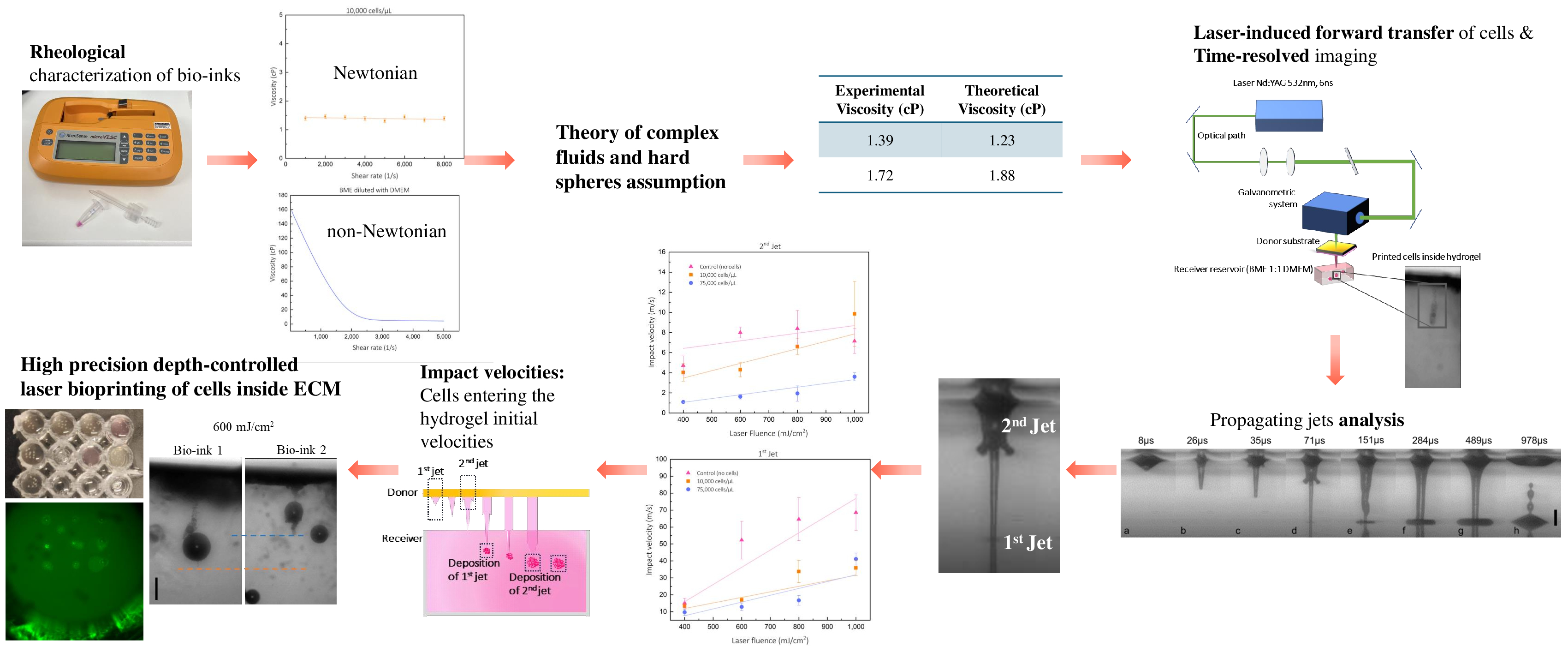
The viscosities of bio-inks were measured using a viscometer–rheometer-on-a-chip (Rheosense, USA), and different shear rate values were applied to characterize them fully. Specifically, μVisc™ viscometer with a 50 μm and/or 200 μm deep flow channel (microVISC A05, range: 0–100 cP, B20, range: 70–10,000 cP) was used at 23 °C. The viscosity of each bio-ink (1, 2, and control) was nearly constant for the range of shear rate values, exhibiting a Newtonian behavior (Table 1, Figure 2A and B). Specifically, for Bio-ink 1 (low number cell density), the shear rates applied were from 800 to 8000 s–1, resulting in viscosity measurements with a mean value of 1.39 cP. The exact measurements were performed with Bio-ink 2 (high number cell density), resulting in a viscosity of 1.72 cP (Figure 2A and B). To confirm the Newtonian behavior of bio-inks and to correlate the dependence of viscosity on cell density, a study based on the theory of complex fluids and hard spheres assumption was applied.23,24 The volume fraction, or the number of cells suspended in the media, can be calculated by dividing the total volume of the cells by the total suspension volume, presented in Equation (I).

Figure 2. Rheological characterization of (A) Bio-ink 1 (low number cell density) and (B) Bio-ink 2 (high number cell density), showcasing Newtonian behavior. (C) Rheological characterization of BME diluted with DMEM, showing Bingham plastic-like behavior. Abbreviations: BME, basement membrane extract; DMEM, Dulbecco’s Modified Eagle Medium.
where Vcells represents the volume of cells, N the number of cells, and α the radius of each cell. Vtotal represents the total volume of the media added to the suspension to reach the desired concentration. The calculated volume fractions of Bio-ink 1 and Bio-ink 2 are φ1 = 2% and φ2 = 16%, respectively, assuming a mean cell diameter of 15 μm. It was reported that for volume fractions between 30% and 49%, the particle-containing fluid exhibits a shear-thinning behavior and, for over 45%, a shear thickening.24,25 For lower volume fractions (φ < 30%), which is the case for both bio-inks, the predicted behavior shows a constant viscosity for varying shear rates, confirming their Newtonian behavior.26 Based on the above theory, the theoretical values of viscosities can be calculated using Equation (II).
where ηm is the viscosity of the suspending medium, φ refers to the aforementioned volume fraction, and φmax is the maximum packing volume fraction of particles. The maximum volume fraction for a fluid is 0.5%, as demonstrated by theory and simulations because the material crystallizes above this point.23 The theoretical viscosity values calculated for Bio-ink 1 and Bio-ink 2 are 1.23 and 1.88 cP, respectively, confirming the experimental measurements (Table 1). These results confirm our methodology for calculating the cell-laden bio-ink viscosities based on their volume fraction.
Table 1. Viscosity measurements of bio-inks and comparison with their theoretical values
| Bio-ink | Composition | Experimental viscosity (cP) | Theoretical viscosity (cP) |
|---|---|---|---|
| 1 | 10,000 cells/µL mixed with DMEM (+10% FBS, +1% p.s) |
1.39 | 1.23 |
| 2 | 75,000 cells/µL mixed with DMEM (+10% FBS, +1% p.s) |
1.72 | 1.88 |
| Control | DMEM (+10% FBS, +1% p.s) | 1.2 | - |
Abbreviations: DMEM, Dulbecco’s Modified Eagle Medium; FBS, fetal bovine serum; p.s, penicillin and streptomycin.
Diluted BME with DMEM was also characterized using μVisc™ by applying different shear rate values from 50 to 5000 s–1. It was proven to behave as a nonNewtonian material (Figure 2C). At lower shear rates (50 and 100 s–1), the viscosity had a higher value, reaching 140 and 160 cP, respectively, and by increasing it, the values decreased significantly, reaching 4 cP at 5000 s–1 shear rates. Interestingly, BME follows Bingham’s plastic-like behavior.2 As a Bingham plastic fluid, it behaves as a Newtonian fluid above a shear rate threshold. However, at lower rates, it behaves as an elastic solid body.
3.2. Analysis of the produced jets before extracellular matrix penetration.
The presence of two successive jets throughout the printing process has been reliably noted in several studies.27–29 However, only a small number of groups have thoroughly examined the unique properties of these jets and their function in the printing process as a whole.25,26 The impact velocities of both primary and secondary jets play an essential role in the final depth immobilization of cells inside the BME. Calculating the impact velocities involved extracting relevant frames from the recorded video sequences, accompanied by measurements of the front edge of each jet for both bio-inks (Fiji, Image J software). The primary jet is generated when the cavitation bubble implodes, and less than 30 μs later, a secondary jet appears, as previously shown by Cerbus et al.30 This secondary jet originates from the secondary flow caused by the bubble dynamics rather than from the expansion of a secondary bubble, as seen with the first jet. When the focused laser beam hits the donor’s surface, the local evaporation from the absorption of the donor absorbing layer material creates a cavitation bubble, and its implosion pushes the bio-ink toward it, generating the primary jet.30
Four laser fluences were investigated in this study in relation to their impact velocities and the corresponding immobilization depths at which cells were deposited; however, only the 600 mJ/cm2 fluence was focused on regarding the jets’ properties. Figure 3 presents the jets captured by the high-speed camera setup for all the investigated laser fluences for both bio-inks (Figure 3), supported by Videos S1–S16, Supporting Material, where all the captured videos are reported.

Figure 3. High-speed camera images of the successive jets for both bio-inks and all laser fluences 80 μs after the cavitation bubble implosion. It can be observed that the secondary jet for (A) Bio-ink 1 precedes the respective secondary jet of the (B) Bio-ink2 for all the laser fluences, indicating a higher velocity when the bio-ink contains fewer cells. See Videos S1–S16, Supporting Information, for the recorded processes. Scale bar: 250 µm.
The primary jet is very thin in diameter and rapid, as shown in Figure 4, while the secondary jet is thicker and slower. Specifically, for control and Bio-ink 1 and Bio-ink 2 at 8 and 13 μs, respectively, the cavitation bubble expands, producing the primary jet, which propagates toward the receiver surface. The primary jet’s lifespan ends when the secondary jet’s front edge is about to hit the receiver at 124, 151, and 366 μs, respectively. The generation of the secondary jet occurs 30 μs after the implosion of the cavitation bubble, continuously feeding the already formed printed droplet (from the primary jet) in the receiver. This behavior is observed in all different laser fluences and bio-ink types applied in this study.

Figure 4. Jet propagation of (A) control, (B) Bio-ink 1 (low number cells density), and (C) Bio-ink 2 (high number cells density) for laser fluence of 600 mJ/cm2. Impact velocities versus laser fluences for primary and secondary jets (D) Bio-ink 1 and (E) Bio-ink 2. Scale bar: 250 μm.
The primary jet’s average thickness, or the diameter of the cylindrical shape, is measured at 45 μm, while the secondary jet has a diameter of 170 μm, making it approximately four times thicker than the primary jet. As the cell concentration in bio-ink increases, while keeping the laser fluence constant, the primary jet becomes slower, resulting in a lower velocity for the front edge of the secondary jet. The lifespan of the primary jet for Bio-ink 1 is 148 μs, for Bio-ink 2 is 353 μs, and for the control, it is 116 μs. The secondary jet lasts an average of 900 μs for all types of bio-inks, showing almost equal lifespan among them. The whole printing phenomenon observed in Area A lasted approximately 1 ms, with the lifespan of the secondary jet being three to eight times longer than the primary one. While the lifespan of the primary jets varies significantly amongst bio-inks until they reach the receiver substrate, the secondary jets among all bio-inks have almost the same lifespan.
Four laser fluences (400, 600, 800, and 1000 mJ/cm2) were investigated to observe the differences in immobilization depths inside the BME hydrogel. Impact velocities of both Bio-ink 1 and Bio-ink 2 were calculated using the two final successive frames obtained before the front edge of each jet hit the receiver. For both bio-inks, it is confirmed that the values of the impact velocities of the primary jet, for all the laser fluences, are considerably higher than the ones for the secondary jets (Figure 4). The range of impact velocities of primary jets for Bio-ink 1 is 10–40 m/s, while for the secondary jet, it varies between 1 and 10 m/s. For Bio-ink 2, the impact velocities of the primary jet are slightly lower than that of Bio-ink 1, while the secondary jets’ impact velocities range from 1 to 3 m/s. The reproducibility of the results deteriorates as the laser fluence increases. The generated jets are turbulent at higher laser fluences, such as 800 and 1000 mJ/cm2, making the printing process non-reproducible.31 Notably, for the primary jet, the same impact velocity was found in the case of 1000 mJ/cm2 for both bio-inks.
3.3. Effect of the impact velocity and cell concentration on the precise penetration depth
Comparing the two types of bio-inks, it is deduced that the low cell concentration Bio-ink 1 undergoes a more rapid evolution compared to the high cell density Bio-ink 2. Bio-ink 2, which has a higher amount of “microparticles” in suspension, has a higher viscosity than Bio-ink 1, as confirmed by the agreement between theoretical and experimental calculations and measurements of the bio-ink viscosities. This increased velocity results in a lower front edge velocity when the jet enters the matrix. Consequently, the cells in the less viscous bio-ink can be immobilized at a greater depth inside the BME diluted with DMEM hydrogel.
Figure 5 shows the comparison of impact velocities among the three bio-inks for the primary (Figure 5A) and the secondary (Figure 5B) jets. The control bio-ink has a higher impact velocity, confirming the previous results. To enable the controlled immobilization of cells at any desired depth inside the BME, the setup in Figure 1 was used, imaging the printed cells inside the BME through the transparent container (Area B). By increasing the laser fluence, the impact velocities increased, resulting in the deposition of cells in higher depths inside the matrix. In regards to the primary jet, the control bio-ink demonstrates the highest impact velocities among the three bio-inks, in the range of 15–80 m/s. For Bio-ink 1 and Bio-ink 2, the impact velocities of the primary jet are calculated between 13–36 and 9–40 m/s, respectively, for all laser fluences. For the range of laser fluences employed in this study, a clear pattern of increasing impact velocities attributed to increasing laser energies was observed, except for 1000 mJ/cm2, which demonstrated turbulent effects during printing. The turbulent effect is more distinct during primary jet evolution due to the existing high velocities of these jets. Regarding the secondary jet, which develops quite a lower impact velocity than the primary jet, it follows a clearer trend among the three types of bio-inks, mainly because of its inherent stability during propagation. The control bio-ink demonstrates the highest impact velocities, from 4 to 8 m/s. Bio-ink 1 exhibits velocities from 4 to 10 m/s, while Bio-ink 2 exhibits velocities from 1 to 3.5 m/s. The propagation of the secondary jet is more stable in terms of impact velocities versus laser fluence and its reproducibility compared to the primary jet, which, due to its small lifespan, provides less reliable conclusions about bio-ink printing propagation. The secondary jet shows a distinctive differentiation between the two cell-laden bio-inks. Measurements of the control bio-ink demonstrate that, when using the same material as a base for the bio-inks composition (e.g., in this study, we used DMEM), the cell-free bio-ink has the most rapid propagation during LIFT printing, in contrast to the cell-laden bio-inks.

Figure 5. Comparison of impact velocities among three bio-inks between (A) primary and (B) secondary jets.
Each jet plays an essential role in the precise immobilization of the cells inside the BME. The impact velocities of the primary jet are the initial velocities for entering the BME receiver, determining the ability to puncture the soft gel and opening a path followed by the secondary one. Figure 6A and B shows that the cells penetrate deeper inside the matrix by increasing the laser fluence. Measurements demonstrate that when printing Bio-ink 1, cells can be immobilized precisely at 1.8 mm for 400 mJ/cm2. Additionally, when the laser fluence is increased by 200 mJ/cm2, the penetration depth increases by about 0.3 mm, reaching the maximum penetration depth of 2.8 mm for 1000 mJ/cm2. In the case of laser printing Bio-ink 2, cells are immobilized at a depth of 1.3 mm at 400 mJ/cm2 and up to 2.3 mm at 1000 mJ/cm2.

Figure 6. Controlled depth immobilization of cells inside diluted BME with DMEM versus laser fluence. Comparison of the final immobilization depth of cells inside BME with DMEM regarding Bio-ink 1 and Bio-ink 2 for all the under-investigation laser fluences at (A) 400 mJ/cm2, (B) 600 mJ/cm2, (C) 800 mJ/cm2, and (D) 1000 mJ/cm2. (E) Graphical comparison between the immobilization depths versus laser fluence for each cell-laden bio-ink. The orange color indicates Bio-ink 1 with 10,000 cells/µL, and the blue color indicates Bio-ink 2 with 75,000 cells/µL. Scale bar: 500 µm. See Videos S1–S16, Supporting Information for the recorded processes. Abbreviations: BME, basement membrane extract; DMEM, Dulbecco’s Modified Eagle Medium.
Apart from laser fluences, the viscosity of the bio-inks is a crucial characteristic that determines the penetration depth of the printed cells. For Bio-ink 1, it is observed that the cells are immobilized at higher depths, which contradicts the higher cell density of Bio-ink 2. In summary, when the bio-ink contains fewer cells, i.e., lower volume fraction and thus lower viscosity value, it results in an increasing motion of the cells inside the matrix, and finally, cells are immobilized at higher depths inside the BME.
During the bioprinting process, the impact velocity is in the range of several m/s, while the BME substrate remains stagnant. This creates a high-velocity gradient between the penetrating jet and BME hydrogel, resulting in high shear rates. The latter is associated with the BME being light and viscous (~4 cP), allowing the penetration of the jet carrying the cells. As the penetrating jet decelerates, the velocity gradient declines, leading to lower shear rates and a higher viscosity value of BME (~160 cP). The interaction between the penetrating jet and the BME matrix terminates when the shear rate reaches values where the BME enters the plastic region (Figure 2C), immobilizing cells at the corresponding depth.
As a demonstrative application of the developed protocol, Bio-ink2 was utilized for laser printing within a BME matrix in a pattern of nine droplets. The printed structures were monitored for 7 days post-printing using an inverted fluorescent microscope (Leica DMIRE2, Leica, Germany). Due to the challenges of capturing live structures along the z-axis (depth), imaging was performed using the inverted fluorescent microscope. In contrast, all other images in this study were acquired as snapshots using a high-speed camera setup, enabling detailed imaging within the hydrogel.
On Day 0 (the day of printing), cells were successfully printed within the BME matrix at the specified depths (Figure 7, top, 4× magnification) across all tested laser fluences. This indicates that the laser fluences employed are effective for cell printing and do not compromise cell viability, as confirmed by fluorescent microscopy, which demonstrated that the cells remained viable and alive.

Figure 7. (A) Laser printing of cells at 75,000 µL–1 inside BME for four laser fluences. Monitoring of the printing cells until 7 days post printing, where they form bigger scale spheroids. (B) Images from both brightfield and fluorescent microscopes were focused at 600 mJ/cm2 inside BME throughout the days after printing. (C) Printing cells on Day 0 illuminated by LED right after printing on Day 7, where all the printed droplets formed spheroids, visible to the naked eye. Scale bars: 500 µm, magnification: 4× and 10×.
Printed cells were subsequently imaged every 2 days, up to Day 7, during which each printed droplet formed a larger spheroid exceeding 500 µm in diameter. Laser bioprinting within the BME matrix was achieved at 75,000 cells/µL cell density across varying laser fluences. Monitoring over 7 days revealed progressive spheroid growth, with notable results observed at a laser fluence of 600 mJ/cm². Brightfield and fluorescent microscopy confirmed the successful immobilization and aggregation of cells into spheroids by Day 7. Additionally, LED illumination immediately post-printing highlighted the uniformity of printed droplets, while spheroid formation was visibly evident across all conditions by Day 7, even to the naked eye.
These findings underscore the efficacy of laser bioprinting in achieving precise cell placement and controlled 3D cellular organization within an ECM toward 3D structures.
4. Discussion
This study presents a novel approach for achieving high-precision, depth-controlled bioprinting of cells within an ECM using the LIFT technique. By leveraging the unique properties of laser-assisted bioprinting, we successfully demonstrated the controlled immobilization of cells at predefined depths, addressing a key challenge in 3D bioprinting for tissue engineering and regenerative medicine applications. The findings of this study provide insights into the bioprinting process at a microstructural level and establish a reproducible methodology for precise cell deposition in soft biomaterials.
The rheological characterization of the bio-inks played a crucial role in understanding their behavior during printing. Our results confirm that cell-laden bio-inks, prepared with DMEM supplemented with FBS and antibiotics, exhibit Newtonian behavior. Bio-ink 1, containing 10,000 cells/µL, had a viscosity of 1.39 cP, while Bio-ink 2, with 75,000 cells/µL, exhibited a slightly higher viscosity of 1.72 cP. These experimental values align well with theoretical predictions based on the volume fraction of suspended cells.
Conversely, the ECM substrate, composed of BME diluted with DMEM, displayed Bingham plastic-like behavior. This property significantly influenced the penetration depth of printed cells, as the ECM behaved as a viscous fluid at high shear rates during jet propagation and as a semi-solid at lower shear rates, enabling controlled immobilization of the cells at precise depths.
Delrot et al.2 achieved a controlled liquid deposition inside a Gelatin 3D soft matrix, where the bio-ink utilized contained fluorescent beads. They achieved the highest immobilization depth at 300 µm without imaging the printed structures inside the hydrogel. In contrast, our study advanced the application of LIFT by utilizing live cell-laden bio-inks, which were characterized by their rheology. The imaging achieved in observation Area B (i.e., inside the hydrogel) validated the final immobilization depth of cells. Specifically, a key observation in this study was the formation of two sequential jets during the LIFT process. Cerbus et al. extensively studied two successive jets’ observations during laser printing,30 with theoretical and experimental results showcasing their existence and the velocities they retrieve. The bio-ink that they utilized was water, while in our study, we attempted to investigate the existence of the two successive jets of two cell-laden bio-inks. It is observed that the primary jet exhibits high impact velocity and punctures the ECM, while the secondary jet, which followed the path created by the primary jet, delivered additional cells and finalized immobilization depth. The high-speed imaging system allowed a detailed analysis of these jets, revealing that their velocities were directly influenced by laser fluence and bio-ink viscosity. The primary jets of Bio-ink 1 consistently exhibited higher impact velocities than Bio-ink 2 due to the lower viscosity and reduced cellular content, resulting in deeper cell penetration within the ECM.
We observed a clear correlation between energy input and immobilization depth by systematically varying laser fluence from 400 to 1000 mJ/cm². At 1000 mJ/cm², Bio-ink 1 achieved immobilization depths exceeding 2.8 mm, while Bio-ink 2 reached a maximum depth of 2.3 mm due to its higher viscosity. This confirms that bio-ink composition and rheological properties are pivotal in determining final deposition depth.
Post-printing analysis of the immobilized cells over 7 days further validated this method’s effectiveness. Fluorescence microscopy imaging confirmed high cell viability immediately after printing, with continued proliferation and spheroid formation observed throughout the study. The ability to control cell distribution within a 3D matrix while maintaining viability highlights the potential of LIFT bioprinting for generating functional tissue structures.
The ability to precisely deposit cells at specific depths within an ECM opens new avenues for applications in tissue engineering, drug testing, and regenerative medicine. The demonstrated methodology could be adapted for constructing complex, multi-layered cell structures, closely mimicking in vivo conditions. Future research should explore the integration of additional cell types and ECM compositions to assess the adaptability of this technique across various tissue models. Additionally, optimizing laser parameters for improved reproducibility and investigating the mechanical stability of printed structures over extended periods will be critical for translational applications.
This study establishes a robust framework for depth-controlled bioprinting using LIFT, providing valuable insights into the interplay between bio-ink properties, jet dynamics, and cell immobilization depth. By refining these parameters, we move closer to the goal of fabricating engineered tissues with precise spatial organization, paving the way for advancements in bioprinting technology and its biomedical applications.
5. Conclusion
This paper demonstrates precise laser printing and controlled cell immobilization inside an ECM. A commercially available soft hydrogel ECM was used as a receiver substrate to examine the bio-ink’s deposition depth. The study analyzes the formation of two sequential jets during laser bioprinting, which is crucial for cell penetration into ECM. It explores the interplay between bio-ink rheology at different cell concentrations and jet formation, affecting final immobilization depth. Rheological characterization revealed that bio-inks exhibit Newtonian behavior at specific volume fractions, while the ECM behaves as a Bingham-like plastic, facilitating bioprinting. The laser pulse induces a significant amount of shear rate to the bio-ink, resulting in a high shear rate that causes the viscosity’s value to change.32
Cells were immobilized at depths exceeding 2.5 mm, with less viscous bio-inks penetrating deeper than more viscous ones. By tuning laser energy, controlled-depth bioprinting of bio-inks with varying cell densities (10,000 and 75,000 cells/µL) was achieved. Laser fluences of 400– 1000 mJ/cm², safe for cell viability, were applied. Hence, it examines the correlation of penetration depth with laser parameters (laser energy) and cell concentration. This study focuses on creating a protocol to immobilize cells at predetermined depths via the LIFT technique, according to the requirements and the specifications imposed by the user. There is no optimal fluence; each fluence results in distinct immobilization depths. This creates not a parametric study but a practical methodology for precise in-depth cell printing tailored to user specifications and enabling bio-fabrication of complex architectures. These findings may impact ex vivo tissue modeling and potential in vivo grafting by offering a controlled, reproducible approach to additive cell printing on existing substrates.
1.Chliara MA, Elezoglou S, Zergioti I. Bioprinting on organ-on-chip: development and applications. Biosensors. 2022;12(12):1135.
doi: 10.3390/bios12121135
2.Delrot P, Hauser SP, Krizek J, Moser C. Depth-controlled laser-induced jet injection for direct three-dimensional liquid delivery. Appl Phys A. 2018;124(9):616.
doi: 10.1007/s00339-018-2030-6
3.Hinton TJ, Jallerat Q, Palchesko RN, et al. Three-dimensional printing of complex biological structures by freeform reversible embedding of suspended hydrogels. Sci Adv. 2015;1(9):e1500758.
4.Catros S, Guillotin B, Bačáková M, Fricain J-C, Guillemot F. Effect of laser energy, substrate film thickness and bioink viscosity on viability of endothelial cells printed by Laser-Assisted Bioprinting. Appl Surf Sci. 2011;257(12):5142-514.
doi: 10.1016/j.apsusc.2010.11.049
5.Elkaseer A, Chen KJ, Kuchta M, Scholz SG. On the quantitative assessment of the effect of multiple process parameters on the printed layer height in 3D inkjet printing. Virtual Phys Prototyp. 2023;18(1):e2269898.
doi: 10.1080/17452759.2023.2269898
6.Gruene M, Pflaum M, Deiwick A, et al. Adipogenic differentiation of laser-printed 3D tissue grafts consisting of human adipose-derived stem cells. Biofabrication. 2011;3(1):015005.
doi: 10.1088/1758-5082/3/1/015005
7.Gruene M, Pflaum M, Hess C, et al. Laser printing of three-dimensional multicellular arrays for studies of cell-cell and cell-environment interactions. Tissue Eng Part C Methods. 2011;17(10):973-982.
doi: 10.1089/ten.TEC.2011.0185
8.Catros S, Fricain JC, Guillotin B, et al. Laser-assisted bioprinting for creating on-demand patterns of human osteoprogenitor cells and nano-hydroxyapatite. Biofabrication. 2011;3(2):025001.
doi: 10.1088/1758-5082/3/2/025001
9.Koch L, Deiwick A, Franke A, et al. Laser bioprinting of human induced pluripotent stem cells-the effect of printing and biomaterials on cell survival, pluripotency, and differentiation. Biofabrication. 2018;10(3):035005.
10.Sorkio A, Koch L, Koivusalo L, et al. Human stem cell based corneal tissue mimicking structures using laser-assisted 3D bioprinting and functional bioinks. Biomaterials. 2018;171:57-71.
doi: 10.1016/j.biomaterials.2018.04.034
11.Antoshin AA, Churbanov SN, Minaev NV, et al. LIFTbioprinting, is it worth it? Bioprinting. 2019;15:e00052.
doi: 10.1016/j.bprint.2019.e00052
12.Guillotin B, Souquet A, Catros S, et al. Laser assisted bioprinting of engineered tissue with high cell density and microscale organization. Biomaterials. 2010;31(28):7250-7256.
doi: 10.1016/j.biomaterials.2010.05.055
13.Karakaidos P, Kryou C, Simigdala N, Klinakis A, Zergioti I. Laser bioprinting of cells using UV and visible wavelengths: a comparative DNA damage study. Bioengineering. 2022;9(8):378.
doi: 10.3390/bioengineering9080378
14.Murphy SV, Atala A. 3D bioprinting of tissues and organs. Nat Biotechnol. 2014;32(8):773-785.
doi: 10.1038/nbt.2958
15.Santos SC, Custódio CA, Mano JF. Human protein-based porous scaffolds as platforms for Xeno-free 3D cell culture. Adv Healthc Mater. 2022;11(12):2102383.
16.Skrepetos S, Ranella A, Farsari M. 3D injectable mechanical metamaterials for tissue engineering applications. In: Conference on Lasers and Electro-Optics/Europe (CLEO/Europe 2023) and European Quantum Electronics Conference (EQEC 2023), paper cm_p_3. Optica Publishing Group; 2023: cm_p_3. Accessed: Sep. 20, 2024. [Online]. Available: https://opg.optica.org/abstract.cfm?uri=CLEO_Europe-2023-cm_p_3
17.Ren Y, Yang X, Ma Z, et al. Developments and Opportunities for 3D Bioprinted Organoids. Int J Bioprint. 2021; 7(3):364.
18.Richards DJ, Li Y, Kerr CM, et al. Human cardiac organoids for the modelling of myocardial infarction and drug cardiotoxicity. Nat Biomed Eng. 2020;4(4):446-462.
doi: 10.1038/s41551-020-0539-4
19.Leite SB, Roosens T, El Taghdouini A, et al. Novel human hepatic organoid model enables testing of drug-induced liver fibrosis in vitro. Biomaterials. 2016;78:1-10.
doi: 10.1016/j.biomaterials.2015.11.026
20.Paraskevopoulou V, Papafotiou G, Klinakis A. KRT14 marks bladder progenitors. Cell Cycle. 2016;15(23):3161-3162.
doi: 10.1080/15384101.2016.1220722
21.Daly AC, Davidson MD, Burdick JA. 3D bioprinting of high cell-density heterogeneous tissue models through spheroid fusion within self-healing hydrogels. Nat Commun. 2021;12(1):753.
doi: 10.1038/s41467-021-21029-2
22.Jalaal M, Li S, Klein Schaarsberg M, Qin Y, Lohse D. Destructive mechanisms in laser induced forward transfer. Appl Phys Lett. 2019;114(21):213703.
doi: 10.1063/1.5095520
23.Wagner NJ, Mewis J, eds. Theory and Applications of Colloidal Suspension Rheology, 1st ed. Cambridge University Press; 2021.
24.Denn MM, Morris JF, Bonn D. Shear thickening in concentrated suspensions of smooth spheres in Newtonian suspending fluids. Soft Matter. 2018;14(2):170-184.
doi: 10.1039/C7SM00761B
25.Stickel JJ, Powell RL. Fluid mechanics and rheology of dense suspensions. Annu Rev Fluid Mech. 2005;37(1):129-149.
doi: 10.1146/annurev.fluid.36.050802.122132
26.Pal R. Recent Progress in the viscosity modeling of concentrated suspensions of unimodal hard spheres. ChemEngineering. 2023;7(4):70.
doi: 10.3390/chemengineering7040070
27.Patrascioiu A, Fernández-Pradas JM, Palla-Papavlu A, Morenza JL, Serra P. Laser-generated liquid microjets: correlation between bubble dynamics and liquid ejection. Microfluid Nanofluid. 2014;16(1–2):55-63.
doi: 10.1007/s10404-013-1218-5
28.Unger C, Gruene M, Koch L, Koch J, Chichkov BN. Time-resolved imaging of hydrogel printing via laser-induced forward transfer. Appl Phys A. 2011;103(2):271-277.
doi: 10.1007/s00339-010-6030-4
29.Chen RCC, Yu YT, Su KW, Chen JF, Chen YF. Exploration of water jet generated by Q-switched laser induced water breakdown with different depths beneath a flat free surface. Opt Express. 2013;21(1):445.
doi: 10.1364/OE.21.000445
30.Cerbus RT, Chraibi H, Tondusson M, et al. Experimental and numerical study of laser-induced secondary jetting. J Fluid Mech. 2022;934:A14.
31.Ali M, Pages E, Ducom A, Fontaine A, Guillemot F. Controlling laser-induced jet formation for bioprinting mesenchymal stem cells with high viability and high resolution. Biofabrication. 2014;6(4):045001.
doi: 10.1088/1758-5082/6/4/045001
32.Kalaitzis A. Jetting dynamics of Newtonian and non-Newtonian fluids via laser-induced forward transfer: experimental and simulation studies. Appl Surf Sci. 2019;465:136-142.