

Biological 3D-printed viscoelastic scaffolds with controllable stress relaxation rates

The natural extracellular matrix (ECM) exhibits remarkable viscoelasticity and stress relaxation. Constructing viscoelastic scaffolds that can precisely control the stress relaxation rate and possess good biocompatibility is a key challenge in the design of tissue engineering scaffolds. Understanding the factors influencing the viscoelasticity of scaffolds and their mechanisms, as well as implementing comprehensive regulatory strategies based on this understanding, are effective methods for precisely controlling the stress relaxation rate. Current research on viscoelastic scaffolds mainly focuses on the regulation of bulk hydrogel viscoelasticity, while the impact of 3D printing parameters on stress relaxation time remains underexplored. In this study, we controlled the structure and morphology of silk fibroin to obtain a crystalline silk fibroin fiber (SL) solution, which was then mixed with gelatin solution to achieve high-precision printing of low-concentration (<2%) silk fibroin. Based on this, we explored the effects of printing angle, fiber diameter, and porosity on the stress relaxation rate and elastic modulus of the scaffold. Specifically, as porosity increases, the relaxation rate tends to rise, while the elastic modulus decreases. Conversely, as the printing angle and fiber diameter increase, the relaxation rate significantly decreases, and the elastic modulus correspondingly increases. We verified these effects using alginate-based bioink, demonstrating the universality of the influence of printing parameters on scaffold viscoelasticity. Additionally, we constructed scaffolds with similar elastic moduli but different stress relaxation rates and investigated their effects on cell growth, thereby confirming the good biocompatibility of viscoelastic scaffolds. This study not only provides a theoretical basis for precisely controlling the stress relaxation rate of 3D-printed viscoelastic scaffolds but also offers new insights for the design and optimization of tissue engineering scaffolds.
1. Introduction
The extracellular matrix (ECM) serves not only as a structural scaffold but also as a provider of 3D biochemical and biophysical cues that regulate cell adhesion, stretching, proliferation, and differentiation.1,2 Mechanical signals are considered one of the key elements in modulating cell/tissue behavior. Extensive research has demonstrated that the elastic modulus of scaffolds can determine cell differentiation and phenotypic behavior, and improving tissue repair quality through the regulation of scaffold elastic modulus has become a research hotspot in the field of tissue engineering.3–5 Researchers have deeply explored the regulatory patterns and mechanisms of scaffold elastic modulus. However, recent studies have indicated that the ECM exhibits viscoelasticity, and its response to deformation or mechanical loading is time-dependent.6,7 Increasing evidence suggests that matrix viscoelasticity may be an important and unique microenvironmental parameter that guides cell behavior and fate, playing a crucial role in growth and development, homeostasis maintenance, and tissue regeneration.8
Biological 3D printing is a layer-by-layer deposition bio-automated manufacturing technology that can be used to print various biomaterials, customize scaffold parameters, and arrange biomaterials, molecules, and cells. 3D printing technology allows for the personalized design of complex 3D microstructures, enabling the construction of biomimetic functionalized tissues, and has made significant advancements in the biomedical field in recent years. Currently, the most widely used biological 3D printing technologies include inkjet printing,9 extrusion printing,10 and digital light processing (DLP).11 Among these, extrusion printing is the most widely used in the field of biomanufacturing. Extrusion-based biological 3D printing typically utilizes uncrosslinked bioink precursors for printing, followed by post-processing crosslinking to stabilize the scaffold structure.
The stress relaxation rate serves as a critical metric for evaluating the viscoelastic properties of a matrix and exerts a substantial influence on various cellular behaviors, including cell diffusion, migration, proliferation, differentiation, and matrix deposition.12,13 The mechanical properties of hydrogels are influenced by a multitude of factors. To date, researchers have successfully modulated the viscoelasticity of hydrogels by varying the molecular weight or chain length of polymer chains, adjusting the concentration or crosslinking density of the polymers, and altering the strength of both non-covalent and covalent interactions.14 For instance, within the alginate (Alg)-polyethylene glycol (PEG) hydrogel system, stress relaxation can be effectively controlled by manipulating the density of PEG through adjustments in its total amount.6 Similarly, low-temperature treatment enhances hydrogen bonding interactions, thereby facilitating the regulation of polyvinyl alcohol (PVA); polyvinylpyrrolidone (PVP) hydrogel viscoelasticity as a function of low-temperature cycling times and aging duration at 37 °C.15 Additionally, the incorporation of alcohols (either monohydric or polyhydric) significantly impacts the hydrophobic interactions between silk fibroin chains, thereby modulating the content of β-sheet structures and achieving control over the viscoelasticity of alcohol-containing silk fibroin (SF) hydrogels.12 Despite these notable advancements in regulating the viscoelasticity of bulk hydrogels, studies focusing on the viscoelastic properties of 3D-printed scaffolds, particularly through the manipulation of printing parameters, remain relatively limited. Current research in this domain primarily centers on the optimization of bioink properties.16 The specific effects of printing parameters on the stress relaxation rate of 3D-printed scaffolds warrant further investigation.
The formulation of bioinks is a pivotal component in the bioprinting process. As the foundational materials for scaffold construction, bioinks must provide an optimal microenvironment conducive to cell survival, thereby facilitating cell adhesion, proliferation, and migration. Conversely, bioinks with cytotoxic properties may induce cell apoptosis, necrosis, and unpredictable cell cycle arrest.17 SF is a naturally occurring organic polymer that is abundant, biodegradable, mechanically strong, and highly biocompatible, making it a promising choice for the design of 3D printing bioinks.18 The presence of tyrosine residues (approximately 5%) in SF confers potential for bioconjugation and functionalization in 3D bioprinting applications. However, the inherently low viscosity of SF solutions often necessitates blending with higher-viscosity materials, such as gelatin, and the use of high concentrations of SF (generally reaching 10% or higher) is required to enhance printability.19 This approach not only increases the complexity of solution preparation prior to printing but also results in printed structures with increased rigidity. In practice, achieving rapid (bio)printing with low SF concentrations (<5%) and fabricating complex, fine-structured SF shapes remains a significant challenge.
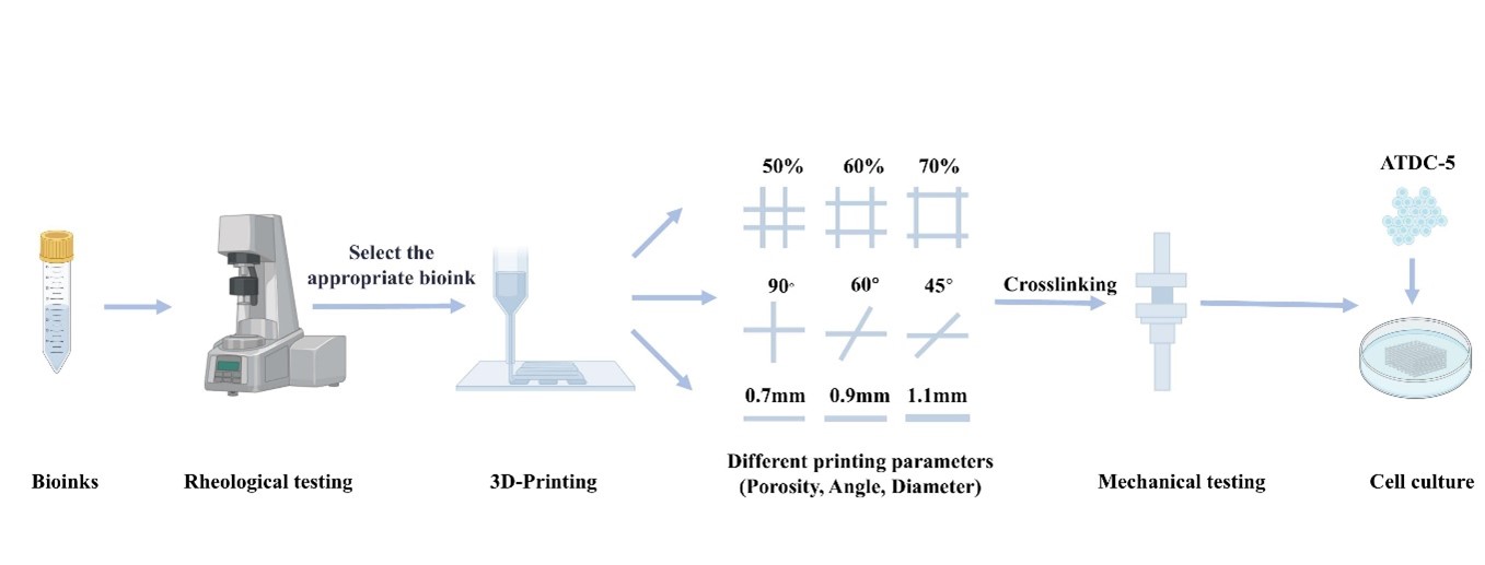
In preliminary studies, we found that ultrasonic treatment of low-concentration SF gel can yield a solution of crystallized silk fibroin fibers (SL). Mixing the SL solution with gelatin can form an SL-gelatin pre-gel, enabling rapid liquid-to-solid transition under low protein concentration conditions.20 However, its printability has not yet been explored. In this work, we employed a bioink composed of gelatin and SL to construct scaffolds through extrusion-based 3D printing (Figure 1). We investigated the effects of printing parameters—specifically, fiber diameter, porosity, and printing angle—on the stress relaxation rate of the scaffolds. Additionally, we evaluated the biocompatibility of the scaffolds through in vitro culture of ATDC-5 chondrogenic cells.

Figure 1. Schematic diagram of the scaffold printed using extrusion-based 3D printing. Abbreviations: SF, silk fibrion; SL, the crystalline silk fibroin fiber solution.
2. Materials and methods
2.1. Materials
This study used the following chemicals and materials: gelatin (Aladdin, China), silkworm silk (Jiaxin, China), 2-morpholinoethanesulphonic acid (MES; Yuanye, China), 1-(3-dimethylaminopropyl)-3-ethylcarbodiimide (EDC; Yuanye, China), N-hydroxy succinimide (NHS; Macklin, China), LiBr (Aladdin, China), Na2CO3 (Aladdin, China), phosphate-buffered saline (PBS; Sunview, China), and sodium alginate powder (Aladdin, China).
2.2. Preparation of printing bioink
The following solutions were prepared using previously reported methods: SF,21 SL,22 SL-gelatin bioink, and gelatin-Alg bioink.23
The SF solution was prepared as follows: 10 g of silk was weighed, and 4.24 g of anhydrous sodium carbonate was added to 100 °C deionized water. The silk was immersed in this solution and boiled for 20 min. Afterward, the silk was removed and washed in deionized water to eliminate sericin. The washed silk was then placed in a 60 °C oven to dry overnight. The dried silk was transferred to a beaker, and 9.3 M LiBr was added. The beaker was placed in a 60 °C oven, where the silk completely dissolved after 4–6 h. Subsequently, the solution was dialyzed for 3 days using a membrane with a cutoff molecular weight of 3500. Finally, the solution was centrifuged to obtain the SF solution.
The SL solution was prepared as follows: the SF solution was concentrated to over 25%, then diluted to the target concentration of 2%. This solution was placed in an oven at 60 °C to induce gelation. The gel was sonicated using a cell disruptor (Shunliu, China) to obtain a transparent SL solution.
The SL-gelatin bioink was prepared as follows: gelatin particles were weighed and dissolved in deionized water to obtain a gelatin solution. This solution was then mixed with the SL solution to prepare a bioink with a concentration of 1.5% for both SL and gelatin. Additionally, a control mixture was prepared using the same ratio and concentration of SF solution and gelatin solution.
The gelatin-Alg bioink was prepared as follows: sodium alginate powder was weighed and dissolved in deionized water to obtain a sodium alginate solution. This solution was then mixed with the gelatin solution to prepare the gelatin-Alg bioink with a concentration of 2.5% for both gelatin and sodium Alg. The formulation and composition of the bioinks are listed in Table 1.
Table 1. Formulation and composition of the bioink
| Bioink | SL/SF/Alg (w/v) | Gelatin (w/v) |
|---|---|---|
| SL-gelatin | 1.5% | 1.5% |
| SF-gelatin | 1.5% | 1.5% |
| Alg-gelatin | 2.5% | 2.5% |
Abbreviations: Alg, alginate; SL: The crystalline silk fibroin fiber solution;. SF: Silk fibroin.
2.3. Rheological analysis
Rheological performance was tested using the method described in previous literature.24 Rheological analysis was conducted using a rotational rheometer (MARS40; HAAKE, Germany) equipped with two concentric parallel plates, maintaining a gap of 1 mm between the plates. The oscillatory amplitude sweep was conducted in stress mode under testing conditions of 0.1–100 Pa at a frequency of 1 Hz. Continuous temperature scanning was performed within a temperature range of 0–40 °C at a rate of 1 °C/min, with a frequency of 1 Hz and a shear stress of 1 Pa. Rotational tests were carried out under conditions ranging from 0.01 to 100 rad/s. All rheological experiments were maintained at the test temperature for 5 min prior to testing to ensure that the materials reached the specified initial temperature. All samples were measured in triplicates.
2.4. Construction of 3D-printed scaffolds
The 3D-printed scaffolds were prepared using a bioprinting platform (Regenovo 3D Bioprinter V2.0; Regenovo 3D Bioprinter V2.0; Regenovo Biotechnology Co., Ltd., China). The formulated bioink was used to print multilayer scaffolds with a cubic shape (10 × 10 × 1.6 mm3) at various printing angles (0°–90°, 0°–60°, and 0°–45°), porosities (50%, 60%, and 70%), and filament diameters (0.7, 0.9, and 1.1 mm). The printing nozzle and platform temperatures were set at 23 and 10°°C, respectively. A 26G needle with an inner diameter of 0.25 mm was used for extrusion, with a fixed extrusion speed of 10 mm/s. After printing, an EDC/NHS/MES solution was added to the scaffolds for crosslinking, followed by washing with PBS to prepare the scaffolds for subsequent experiments.
2.5. Mechanical testing
The mechanical properties of the scaffolds were tested using methods from previous studies.25,26 A universal testing machine (Dongri Instruments, China) equipped with a 100 N load cell was employed to characterize the stress–strain behavior and stress relaxation of the 3D-printed scaffolds. For stress–strain testing, the scaffolds were compressed at a rate of 2 mm/min until a strain of 30% was reached, and the variation of stress with strain was recorded. The elastic modulus (E) was obtained by calculating the relationship between stress (σ) and strain (ε) (Equation I):
For the stress relaxation test, the scaffolds were compressed to a strain of 10% (in the linear region) at a rate of 2 mm/min. From this point, the variation of stress with time was recorded. The half-stress relaxation time is defined as the time required for the stress to decrease from its maximum value to half of that value. All samples were measured in triplicates.
2.6. Porosity measurement
Following the previously published density testing methods,27 the porosity can be calculated using Equation (II):
where is the density of the crosslinked scaffold and is the density of the bulk scaffold obtained through standard molds. All samples were measured in triplicates.
2.7. Degradation experiment
As previously described in the literature,28,29 scaffolds with similar size and morphology were prepared. Before the experiment, the initial mass of each scaffold (W0) was recorded. The scaffolds were then immersed in PBS at 37 °C with a bath ratio of 1:100. After every 24 h, the scaffolds were removed, surface moisture was wiped dry with lint-free paper, and the weight of the scaffolds (W1) was measured. The formula for calculating the degradation rate of the scaffold (weight loss) is defined in Equation (III). For each sample, the tests were conducted in triplicate under the same conditions:
2.8. Printability
Based on previous research,30 an adaptability index (Pr) was utilized to evaluate the printability of the bioink by assessing the printing accuracy of the scaffolds, where L represents the perimeter and A represents the pore area. All samples were measured in triplicates.
2.9. Cell culture
ATDC-5 murine chondrocytes (ATDC-5, FH0378) were obtained from Shanghai Fuheng Biotechnology Co., Ltd. (China). The cells were cultured in DMEM/F12 medium (Meilunbio, China) supplemented with 10% (v/v) fetal bovine serum (FBS; Sunview, China) and 1% (v/v) penicillin-streptomycin (Solarbio, China). Cultures were maintained in a humidified incubator (Forma Steri-Cycle, ThermoFisher) at 37 °C with 5% CO2. When the cells reached 70–80% confluence, they were detached using trypsin-EDTA (Cienry, China) for subsequent experiments.
2.10. Cell seeding
The scaffolds were printed onto circular glass slides and then crosslinked before being transferred to a 12-well plate. After thorough washing with PBS, cells were seeded at a density of 1.5 × 10⁵ cells per sample. The slides were then placed in a controlled incubator for 2 h. After this incubation period, unadhered cells were removed using PBS, and the scaffolds were transferred to a new 12-well plate for further culture.
2.11. Live/dead staining of scaffolds
Cell viability assays were performed on cell-laden scaffolds on days 1 and 7 of culture using a cell viability assay kit (K231206; KeyGEN, China), as previously reported.31 A solution was prepared by mixing 0.5 μL of Calcein-AM and 1 μL of propidium iodide (PI) into 1 mL PBS. Then, 1 mL of the staining solution was added to each well, followed by incubation at room temperature in the dark for 10 min. The scaffolds were washed three times with PBS, with each wash lasting 5 min. Finally, fluorescence images at different wavelengths were captured using a confocal microscope (Nikon, Japan).
2.12. Assessment of cell proliferation
The proliferation rate of ATDC-5 cells seeded on SL-gelatin scaffolds was evaluated using the Cell Counting Kit-8 (CCK-8; Sunview, China), as described in previous literature.32 At designated time points (days 1, 4, and 7), the scaffolds were washed with PBS, and CCK-8 reagent was added to the cell culture medium at a ratio of 10%. After 2 h of incubation, the absorbance was measured using a microplate reader (Varioskan ALF; Thermo Fisher Scientific, USA). The assay was performed in triplicate under identical conditions.
2.13. Data analysis
All measurement values are expressed as mean ± standard deviation. A two-way analysis of variance (ANOVA) was employed to analyze the numerical data and evaluate the effects of different factors on the observed outcomes. The sample size consisted of three replicates for each experimental group, with each measurement performed in triplicate to ensure reproducibility. A p-value < 0.05 was considered statistically significant. The statistical significance of the assays was analyzed and verified using Origin 2021 software (OriginLab Corporation, USA), providing robust support for the findings.
3. Results and discussion
3.1. Rheological characterization of bioink
Appropriate rheological properties are a prerequisite for extrusion-based 3D printing, directly affecting the printability of materials and the quality of printed scaffolds. This work systematically explored the effects of stress, temperature, and shear rate on the rheological properties of SL-gelatin bioink (Figure 2), with a particular focus on their viscosity characteristics.

Figure 2. Rheological analysis of bioinks. (A) Curve of the storage modulus and loss modulus of the bioink as a function of stress. (B) Curves illustrating the storage modulus and loss modulus of the bioink as a function of temperature. (C) Curves depicting the viscosity of the bioink as a function of shear rate (n = 3; f = 1 Hz). Abbreviations: G’, storage modulus; G”, loss modulus; SF, silk fibroin; SL, the crystalline silk fibroin fiber solution.
To define the linear viscoelastic region of the printing bioink, oscillatory amplitude sweep experiments were conducted in stress mode. These experiments facilitated the evaluation of the bioink’s behavior under different stress conditions, allowing for the determination of its yield stress and linear viscoelastic range. The yield stress is defined as the critical stress level at which a material transitions from elastic to plastic deformation, representing the maximum stress that can be applied without causing permanent deformation. The linear viscoelastic range, in contrast, refers to the region where a linear relationship exists between the applied stress and the resulting strain. Within this range, the material exhibits entirely reversible deformation, returning to its original shape upon removal of the external load. The results indicated that the yield stress of SL-gelatin ink was 54.47 ± 9.84 Pa (Figure 2A), reflecting the maximum stress the material can withstand before permanent deformation occurs. The linear viscoelastic region was identified within a strain range of 0–26.19% ± 4.812%, suggesting that within this range, the material maintains good elastic properties, rendering it suitable for fine printing applications. In contrast, the yield stress of SF-gelatin bioink was 10.68 ± 1.42 Pa, with a linear viscoelastic range extending to 0–16.84% ± 5.42% strain, implying that this material can maintain linear viscoelastic behavior over a broader range. At a strain of 1%, all bioinks were within the linear viscoelastic region, providing a stable foundation for subsequent experiments. Therefore, all further experiments were conducted at a strain of 1% to ensure reliable rheological data and more representative results.
Within the linear viscoelastic region at a constant strain of 1%, continuous oscillatory temperature scans were performed on the bioinks over a temperature range of 0–40°C (with a heating rate of 1°C/min and an oscillatory frequency of 1 Hz) to examine the influence of temperature on the storage modulus and loss modulus of the bioinks. The experimental results (Figure 2B) revealed that within the tested temperature range, both SF and SL exhibited minimal fluctuations in modulus, with SL having a significantly higher modulus than that of the same concentration of SF. Additionally, the incorporation of gelatin markedly altered the rheological properties of both SL and SF (Figure 2B). Notably, the storage modulus of SL-gelatin bioink was significantly higher than that of other bioinks, enabling SL-gelatin to maintain greater structural stability and shape retention under various temperature conditions. A higher storage modulus indicates that SL-gelatin can more effectively support external loads during the printing process, thereby enhancing the overall stability of the printed structures. This is particularly important for achieving complex shapes and intricate structures in bioprinting, as the ability to retain structure directly relates to the functionality and biocompatibility of the biomaterials used. It is worth noting that the storage modulus of SL-gelatin bioink began to decline significantly at temperatures above 23°C. To ensure a smooth printing process and maintain the stability of the printed structures, the printing temperature for the bioink was set at 23°C.
Both SL-gelatin and SF-gelatin exhibited shear-thinning behavior, with viscosity rapidly decreasing as the shear rate increased (Figure 2C). Shear thinning, also known as pseudoplasticity, is a notable characteristic of non-Newtonian fluids, where viscosity decreases with an increase in shear rate. The shear-thinning property of the bioink effectively enhances printing fidelity and prevents nozzle clogging.33–35
3.2. Printability
Printing accuracy and shape fidelity are crucial parameters for evaluating the printability of scaffolds. In this study, the Pr value was employed to quantitatively assess printing accuracy (Figure 3A–C). Scaffold structures were printed at angles of 90°, 60°, and 45° using two distinct bioinks (Figure 3). The results indicated that printing accuracy was compromised when using the SF-gelatin bioink (Figure 3D–F). The printed structures exhibited poor shape retention and clarity after extrusion, indicating insufficient printability. The viscosity of the SF solution is low, and its printability is inadequate. Although the viscosity (and consequently the printability) increased after mixing with gelatin solution (Figure 2C), it was still insufficient to maintain a complete printing structure. This finding is consistent with previous studies, where a minimum concentration of 5% (w/v) gelatin is required to maintain solid ink structures during deposition; high-concentration SF-gelatin bioinks typically exhibit better printability, while achieving high-precision printing at low SF concentrations (<5%) remains challenging.36

Figure 3. Comparative analysis of printability. (A–C) Schematic diagrams for the quantification of printing accuracy; Pr > 1 (A), Pr = 1 (B), and Pr < 1 (C). (D–F) Optical images of SF-gelatin scaffolds printed at angles of 90° (D), 60° (E), and 45° (F). (G–I) Optical images of SL-gelatin scaffolds printed at angles of 90° (G), 60° (H), and 45° (I). Scale bars: 1 mm (D–I). Abbreviations: SF, silk fibroin; SL, the crystalline silk fibroin fiber solution; Pr, printing accuracy value.
In contrast, the scaffolds printed with SL-gelatin bioink (Figure 3G–I) exhibited enhanced shape fidelity, with a Pr value of 0.956, nearing the optimal value of 1. This indicated that the printing accuracy of the structures aligned well with the intended design, demonstrating high precision. This observation was consistent with the results of the rheological tests, which revealed that SL-gelatin has a higher initial viscosity and a faster rate of shear thinning. These characteristics collectively contribute to its superior printability, further validating the advantages of the optimized SL-gelatin bioink during the printing process.
In light of the preceding findings, the exceptional performance of SL-gelatin bioink has been of particular interest. To further elucidate its multifunctionality, a range of intricate and demanding geometric configurations were simulated to investigate the applicability of SL-gelatin hydrogel as a bioink. As depicted in Figure 4, anatomically relevant models of human organs—including the nose, ear, and spine—were successfully fabricated via a layer-by-layer extrusion technique. The printed structures exhibited precise replication of the engineered Computer-Aided Design (CAD) designs, indicating that SL-gelatin bioink not only possesses excellent printability and shape fidelity but also effectively addresses complex printing challenges. Collectively, these results substantiated the potential utility of SL-gelatin bioink within the field of bioprinting.

Figure 4. Optical images of organs printed with SL-gelatin bioink. (A) CAD model of the nose. (B) CAD model of the ear. (C) CAD model of the spine. (D) Printed nose model. (E) Printed ear model. (F) Printed spine model. Scale bars: 1 mm (D–F). Abbreviations: CAD, computer-aided design; SL, the crystalline silk fibroin fiber solution.
3.3. Effect of printing parameters on the mechanical properties of scaffolds
3.3.1. Influence of porosity on the mechanical properties of scaffolds
Following the printability assessment of SL-gelatin, we sought to further investigate its mechanical properties and suitability for scaffold design. First, we examined the effect of porosity on the mechanical performance of the scaffolds. In this work, scaffolds with different porosities (50%, 60%, and 70%) were designed (Figure S1A–C, Supporting Information), maintaining a constant printing angle of 90° and a filament diameter of 1.1 mm. The stress–strain relationship of the SL-gelatin scaffolds at these porosity levels was evaluated (Figure 5A). The results indicated that the elastic modulus of the scaffolds significantly decreased with increasing porosity (Figure 5C), consistent with previous findings.

Figure 5. Influence of porosity on the mechanical properties of scaffolds. (A) Stress–strain curves for scaffolds with porosities of 50%, 60%, and 70%. (B) Normalized stress relaxation curves for scaffolds with porosities of 50%, 60%, and 70%. (C) Effect of different printing porosities on the elastic modulus of the scaffolds. (D) Effect of different printing porosities on the half-stress relaxation time of the scaffolds (n = 3; *p ≤ 0.05, **p ≤ 0.01, ***p ≤ 0.001).
Subsequently, stress relaxation tests were conducted on the SL-gelatin scaffolds under a constant strain of 10% (within the linear elastic region). The half-stress relaxation time (τ1/2), defined as the time required for the initial stress to decay to half its value, is a commonly used parameter to characterize the stress relaxation rate of scaffolds. All three groups of scaffolds exhibited rapid stress relaxation phenomena (Figure 5B). Specifically, the τ1/2 for scaffolds with porosities of 50%, 60%, and 70% were 44.063 ± 2.883, 37.067 ± 10.52, and 33.703 ± 5.869 s, respectively. These results indicated a significant decrease in τ1/2 with increasing porosity (Figure 5B and D), demonstrating a negative correlation between τ1/2 and porosity of scaffolds. The increase in porosity led to a more porous scaffold structure, thereby reducing the overall stiffness and energy storage capacity of the scaffolds. The higher porosity reduced the effective load-bearing area of the scaffolds, decreased its continuity, and shortened the stress transfer pathways. This resulted in stress concentration in the limited solid regions, making the high-stress areas more prone to deformation, thus accelerating stress release. Therefore, this phenomenon accelerated the relaxation process of the scaffold.
To further validate this trend, the effects of different porosity levels were also compared at other printing angles. At a printing angle of 60°, the τ1/2 for scaffolds with porosities of 50%, 60%, and 70% were 38.711 ± 2.790, 25.757 ± 2.440, and 25.613 ± 3.400 s, respectively. At a printing angle of 45°, the τ1/2 for the same porosities were 29.558 ± 2.115, 25.600 ± 2.662, and 23.263 ± 2.451 s (Table S1, Supporting Information). These results further support the observed trend that as the porosity of the scaffolds increased, τ1/2 decreased.
3.3.2. Influence of printing angle on the mechanical properties of scaffolds
Furthermore, the effect of the printing angle on τ1/2 of the scaffolds was examined. With a fixed porosity of 50% and a filament diameter of 1.1 mm, scaffolds were designed at three different printing angles: 90°, 60°, and 45° (Figure S1D–F, Supporting Information). The stress–strain curves (Figure 6A) indicated that the elastic modulus of the scaffolds significantly decreased as the printing angle was reduced (Figure 6C).

Figure 6. Influence of printing angle on the mechanical properties of scaffolds. (A) Stress–strain curves for scaffolds printed at angles of 90°, 60°, and 45°. (B) Normalized stress relaxation curves for scaffolds printed at angles of 90°, 60°, and 45°. (C) Effect of different printing angles on the elastic modulus of the scaffolds. (D) Effect of different printing angles on the half-stress relaxation time of the scaffolds (n = 3; **p ≤ 0.01, ***p ≤ 0.001).
During the stress relaxation tests, all three groups of scaffolds exhibited rapid stress relaxation characteristics (Figure 6D). Specifically, the τ1/2 for scaffolds printed at angles of 90°, 60°, and 45° were 44.063 ± 2.883, 38.711 ± 2.790, and 29.558 ± 2.115 s, respectively. These results demonstrated that the τ1/2 of the scaffolds significantly increases as the printing angle decreases, indicating a positive correlation (Figure 6B and D). The difference in stress distribution among scaffolds with different printing angles is the key factor affecting their stress-relaxation rates. In the case of the 90° scaffold, the pores are fully aligned in the vertical direction, resulting in a more uniform stress distribution during compression.26,37 In contrast, scaffolds at 60° and 45° are more prone to stress concentration. The concentrated stress accelerates the viscous flow of the material, leading to faster energy dissipation and thus speeding up the stress relaxation rate. Additionally, scaffolds with 60° and 45° angles are more likely to experience sliding between printed fibers, resulting in a faster stress relaxation rate.
To further validate this trend, the performance of scaffolds at different porosity levels was also compared. When the porosity was fixed at 60%, the τ1/2 for scaffolds at printing angles of 90°, 60°, and 45° were 37.067 ± 10.52, 25.757 ± 2.440, and 25.600 ± 2.662 s, respectively. When the porosity was increased to 70%, the corresponding τ1/2 were 33.703 ± 5.869, 25.613 ± 3.400, and 23.263 ± 2.451 s, respectively (Table S2, Supporting Information). These results further support our conclusion that as the printing angle decreases, the τ1/2 of the scaffolds significantly increases.
3.3.3. Influence of filament diameter on the mechanical properties of scaffolds
Finally, the effect of filament diameter on the stress relaxation rate of scaffolds was investigated. Scaffolds were designed with three filament diameters (0.7, 0.9, and 1.1 mm) while maintaining a fixed printing angle of 90° (Figure S1G–I, Supporting Information). Firstly, we investigated the stress–strain relationship of SL-gelatin scaffolds under compression at a porosity of 50% (Figure 7A). The results indicated that filament diameter significantly influenced the elastic modulus of the scaffolds, with a progressive decrease in elastic modulus as the filament diameter decreased (Figure 7C).

Figure 7. Influence of filament diameter on the mechanical properties of scaffolds. (A) Stress–strain curves for scaffolds with filament diameters of 0.7, 0.9, and 1.1 mm. (B) Normalized stress relaxation curves for scaffolds printed at filament diameters of 0.7, 0.9, and 1.1 mm. (C) Effect of different filament diameters on the elastic modulus of the scaffolds. (D) Effect of different filament diameters on the half-stress relaxation time of the scaffolds (n = 3; *p ≤ 0.05, **p ≤ 0.01, ***p ≤ 0.001).
The results of the stress relaxation tests revealed that the τ1/2 of the scaffolds significantly increases with increasing filament diameter (Figure 7D). Specifically, the τ1/2 for scaffolds with filament diameters of 0.7, 0.9, and 1.1 mm were 19.182 ± 6.064, 28.210 ± 2.243, and 44.063 ± 2.883 s, respectively (Figure 7B and D). The mechanism underlying this phenomenon can be attributed to the microstructural characteristics of the hydrogel. As the bioink, the hydrogel contained a significant amount of water. When the hydrogel was subjected to external forces, the water molecules migrated and rearranged between the molecular chains, facilitating stress release. The migration of water molecules was one of the important mechanisms for stress relaxation in covalently crosslinked scaffolds,38 and the path length of water molecule migration was related to the filament diameter. A larger diameter resulted in a longer migration distance for the water molecules, leading to a slower stress relaxation rate.
The mechanism underlying this phenomenon can be attributed to the microstructural characteristics of the hydrogel. The hydrogel, serving as the ink, contains a large number of water molecules that act as lubricants within the gel network. When the hydrogel is subjected to external forces, these water molecules migrate and rearrange between the molecular chains, facilitating stress release. The migration of water molecules is one of the key mechanisms of stress relaxation in covalently crosslinked scaffolds, and the migration path length is related to the filament diameter. The larger the diameter, the longer the distance the water molecules need to migrate, and the slower the stress relaxation rate.
To further validate this trend, comparative tests were conducted on scaffolds with different porosities. When the porosity was fixed at 60%, the τ1/2 for scaffolds with filament diameters of 0.7, 0.9, and 1.1 mm were 17.603 ± 1.981, 26.312 ± 3.786, and 37.067 ± 10.520 s, respectively. At a porosity of 70%, the corresponding τ1/2 were 20.679 ± 2.777, 25.360 ± 5.140, and 33.703 ± 5.869 s, respectively, for the same filament diameters (Table S3, Supporting Information). These data further confirmed the trend that as filament diameter increases, the half-stress relaxation time of the scaffolds significantly rises.
3.3.4. Influence of printing parameters on the mechanical properties of gelatin-Alg scaffolds
To further explore the universality of the impact of printing parameters on the stress relaxation rate and elastic modulus of scaffolds, gelatin-Alg was used as the bioink, and gelatin-Alg scaffolds were fabricated based on the same printing parameters. A systematic evaluation of their mechanical properties was subsequently conducted.
The results indicated that gelatin-Alg scaffolds exhibit analogous trends to those observed in SL-gelatin scaffolds. Specifically, as the porosity of the scaffolds increased, both the half-stress relaxation time and the elastic modulus significantly decreased (Figure 8A and C). A notable downward trend in the half-stress relaxation time and elastic modulus was observed as the printing angle of the scaffolds decreased (Figure 8A and C). Similarly, reductions in filament diameter were associated with significant declines in both the half-stress relaxation time and the elastic modulus (Figure 8B and D). Scaffolds composed of two distinct materials exhibited similar stress relaxation behaviors, thereby further validating the universality of the influence of printing parameters, such as filament diameter, porosity, and printing angle, on the stress relaxation rate.

Figure 8. Influence of printing parameters on the stress relaxation rate and elastic modulus of gelatin-Alg scaffolds. (A) Effects of printing angle and porosity on the half-stress relaxation time of gelatin-Alg scaffolds. (B) Effect of filament diameter and porosity on the half-stress relaxation time of gelatin-Alg scaffolds. (C) Effect of angle and porosity on the elastic modulus of gelatin-Alg scaffolds. (D) Effect of porosity on the elastic modulus of gelatin-Alg scaffolds (n = 3; *p ≤ 0.05, **p ≤ 0.01, ***p ≤ 0.001). Abbreviation: Alg, alginate.
3.4. Description of ADTC5-to-matrix interaction
To assess the impact of different stress relaxation rates on cell growth, scaffolds with comparable elastic modulus levels but different relaxation rates were constructed using the same bioink and subjected to in vitro cell culture (Table 2).
Table 2. Mechanical properties of scaffolds with different relaxation rates
| Relaxation rate | Relaxation time (s) | Elastic modulus (kPa) | Porosity |
|---|---|---|---|
| 1 | 38.71 ± 2.79 | 3.176 ± 0.469 | 50% |
| 2 | 29.56 ± 2.12 | 3.074 ± 0.802 | 50% |
| 3 | 25.76 ± 2.44 | 3.060 ± 0.416 | 60% |
A 7-day degradation experiment was conducted on the scaffolds. The results indicated that all three groups maintained over 85% of their weight by day 7 (Figure 9), confirming their excellent structural stability, and suggesting that SL-gelatin scaffolds can provide stable physical support for cell adhesion and growth.
Figure 9A–F presents the live/dead staining images taken on days 1 and 7 post-cell seeding. The results demonstrated that SL-gelatin scaffolds exhibit predominant green fluorescence, indicating a high ratio of viable cells within the scaffolds. All groups of scaffolds possess good biocompatibility and did not induce significant cytotoxicity. Additionally, the intact scaffold structures further confirmed their ability to maintain a stable 3D configuration.

Figure 9. SL-gelatin scaffolds. (A–C) Live/dead fluorescence images of scaffolds with different relaxation rates on day 1; Group 1 (A), Group 2 (B), and Group 3 (C). (D–F) Live/dead fluorescence images on day 7; Group 1 (D), Group 2 (E), and Group 3 (F). (G) Degradation rates of scaffolds with varying relaxation rates over 7 days. (H) Optical density (OD) values of scaffolds on days 1, 4, and 7. (I) Proliferation rates of scaffolds on days 4 and 7, highlighting the effects of relaxation rates (n = 3; *p ≤ 0.05, **p ≤ 0.01, ***p ≤ 0.001). Scale bars: 100 µm (A–F). Abbreviation: SL, the crystalline silk fibroin fiber solution.
During the initial stages of cell growth, significant differences in optical density (OD) values were observed on day 1. Groups 1 and 2 had significantly higher OD values compared to Group 3. This difference can be attributed to variations in scaffold porosity. The higher porosity of Group 3 limited the available surface area for cell attachment, thereby affecting the number of cells seeded on the scaffolds. Consequently, Group 1 had a relatively higher cell count, leading to a larger OD value. Conversely, lower porosity provided greater attachment surfaces, resulting in larger OD values (Figure 9H). By day 7, the OD values among the groups displayed no significant differences, indicating that the group with the fastest relaxation rate exhibited the highest growth rate. A quantitative analysis of cell viability over different culture times revealed that scaffolds with faster stress relaxation maintained a rapid growth rate throughout the culture period (Figure 9I). Scaffolds with quicker relaxation rates likely provided a more favorable microenvironment, enhancing cell proliferation potential. SL-gelatin scaffolds demonstrated excellent biocompatibility and provided an ideal growth platform for cells. The relaxation rate of the scaffolds positively influenced cell proliferation, highlighting their potential for applications in tissue engineering.
4. Conclusion
This study employed gelatin combined with treated SF (SL) as bioink, systematically validating the excellent printability of low-concentration SL-gelatin bioink through quantitative analysis of the Pr value, comparative optical imaging, and complex model construction. By conducting mechanical tests on scaffolds fabricated with different printing parameters, we thoroughly investigated the effects of key parameters, such as fiber diameter, printing angle, and porosity, on the mechanical properties of SL-gelatin scaffolds, particularly regarding their regulation of the half-stress relaxation time and elastic modulus. We found that variations in fiber diameter, printing angle, and porosity significantly influenced the stress relaxation behavior of the material. Furthermore, we utilized a composite bioink of gelatin and sodium Alg to verify the universality of the influence of printing parameters on scaffold mechanical properties. The proposed method for modulating the stress relaxation rate of printed scaffolds demonstrated broad applicability and provided theoretical support for the mechanical performance tuning of other printed scaffolds. The promotion of this method will facilitate the development of bio-printed scaffolds with tunable mechanical properties, especially in personalized medical products for applications such as cartilage repair, which holds substantial practical value and theoretical significance. Through this research, we aim to provide new insights for future biomaterial design and tissue engineering, advancing the development of bioprinting technologies in clinical applications.
1.Li J, Chen G, Xu X, et al. Advances of injectable hydrogel-based scaffolds for cartilage regeneration. Regen Biomater. 2019;6(3):129-140.
doi: 10.1093/rb/rbz022
2.Rosales AM, Anseth KS. The design of reversible hydrogels to capture extracellular matrix dynamics. Nat Rev Mater. 2016;1(2):15012.
doi: 10.1038/natrevmats.2015.12
3.Arkenberg MR, Moore DM, Lin C-C. Dynamic control of hydrogel crosslinking via sortase-mediated reversible transpeptidation. Acta Biomaterial. 2019;83: 83-95.
doi: 10.1016/j.actbio.2018.11.011
4.Lin C, Tao B, Deng Y, et al. Matrix promote mesenchymal stromal cell migration with improved deformation via nuclear stiffness decrease. Biomaterials. 2019;217: 119300.
doi: 10.1016/j.biomaterials.2019.119300
5.Jiang T, Xu G, Chen X, et al. Impact of hydrogel elasticity and adherence on osteosarcoma cells and osteoblasts. Adv Healthc Mater. 2019;8(9):1801587.
6.Nam S, Stowers R, Lou J, Xia Y, Chaudhuri O. Varying PEG density to control stress relaxation in alginate-PEG hydrogels for 3D cell culture studies. Biomaterials. 2019;200:15-24.
doi: 10.1016/j.biomaterials.2019.02.004
7.Ding Q, Xu X, Yue Y, et al. Nanocellulose-mediated electroconductive self-healing hydrogels with high strength, plasticity, viscoelasticity, stretchability, and biocompatibility toward multifunctional applications. ACS Appl Mater Interfaces. 2018;10(33):27987-28002.
8.Li T, Hou J, Wang L, et al. Bioprinted anisotropic scaffolds with fast stress relaxation bioink for engineering 3D skeletal muscle and repairing volumetric muscle loss. Acta Biomater. 2023;156:21-36.
doi: 10.1016/j.actbio.2022.08.037
9.Xu T, Zhao W, Zhu J-M, et al. Complex heterogeneous tissue constructs containing multiple cell types prepared by inkjet printing technology. Biomaterials. 2013;34(1):130-139.
doi: 10.1016/j.biomaterials.2012.09.035
10.Moon SH, Park TY, Cha HJ, Yang YJ. Photo-/thermo-responsive bioink for improved printability in extrusion-based bioprinting, Mater Today Bio. 2024;25:100973.
doi: 10.1016/j.mtbio.2024.100973
11.Kim SH, Yeon YK, Lee JM, et al. Precisely printable and biocompatible silk fibroin bioink for digital light processing 3D printing. Nat Commun. 2018;9(1):1620.
doi: 10.103 8/s41467-018-03759-y
12.Kaewprasit K, Kobayashi T, Damrongsakkul S. Thai silk fibroin gelation process enhancing by monohydric and polyhydric alcohols. Int J Biol Macromol. 2018;118: 1726-1735.
doi: 10.1016/j.ijbiomac.2018.07.017
13.Chaudhuri O, Gu L, Klumpers D, et al. Hydrogels with tunable stress relaxation regulate stem cell fate and activity. Nat Mater. 2016;15(3):326-334.
doi: 10.1038/nmat4489
14.Ma Y, Han T, Yang Q, et al. Viscoelastic cell microenvironment: hydrogel-based strategy for recapitulating dynamic ECM mechanics. Adv Funct Mater. 2021;31(24):2100848.
15.Bercea M, Morariu S, Teodorescu M. Rheological investigation of poly(vinyl alcohol)/poly(N-vinyl pyrrolidone) mixtures in aqueous solution and hydrogel state. J Polym Res. 2016;23(142):1-9.
doi: 10.1007/s10965-016-1040-3
16.Bercea M. Rheology as a tool for fine-tuning the properties of printable bioinspired gels. Molecules. 2023;28(6):2766.
doi: 10.3390/molecules28062766
17.Gao Q, Kim B-S, Gao G. Advanced strategies for 3d bioprinting of tissue and organ analogs using alginate hydrogel bioinks. Mar Drugs. 2021;19(12):708.
doi: 10.3390/md19120708
18.Basiri A, Farokhi M, Azami M, et al. A silk fibroin/decellularized extract of Wharton’s jelly hydrogel intended for cartilage tissue engineering. Prog Biomater. 2019;8(1):31-42.
doi: 10.1007/s40204-019-0108-7
19.Rodriguez MJ, Brown J, Giordano J, et al. Silk based bioinks for soft tissue reconstruction using 3-dimensional (3D) printing with in vitro and in vivo assessments. Biomaterials. 2017;117:105-115.
doi: 10.1016/j.biomaterials.2016.11.046
20.Yao D, Li M, Wang T, et al. Viscoelastic silk fibroin hydrogels with tunable strength. ACS Biomater Sci Eng. 2021;7(2):636-647.
doi: 10.1021/acsbiomaterials.0c01348
21.Bashiri Z, Sharifi AM, Ghafari M, et al. In-vitro and in vivo evaluation of angiogenic potential of a novel lithium chloride loaded silk fibroin / alginate 3D porous scaffold with antibacterial activity, for promoting diabetic wound healing. Int J Biol Macromol. 2024;277:134362.
doi: 10.1016/j.ijbiomac.2024.134362
22.Vu T, Xue Y, Vuong T, et al. Comparative study of ultrasonication-induced and naturally self-assembled silk fibroin-wool keratin hydrogel biomaterials. Int J Mol Sci. 2016;17(9):1497.
doi: 10.3390/ijms17091497
23.Gao T, Gillispie GJ, Copus JS, et al. Optimization of gelatin– alginate composite bioink printability using rheological parameters: a systematic approach. Biofabrication. 2018;10(3):034106.
24.Iberite F, Badiola-Mateos M, Loggini S, et al. 3D bioprinting of thermosensitive inks based on gelatin, hyaluronic acid, and fibrinogen: reproducibility and role of printing parameters. Bioprinting. 2024;39:e00338.
doi: 10.1016/j.bprint.2024.e00338
25.Rajput M, Mondal P, Yadav P, Chatterjee K. Light-based 3D bioprinting of bone tissue scaffolds with tunable mechanical properties and architecture from photocurable silk fibroin. Int J Biol Macromol. 2022;202:644-656.
doi: 10.1016/j.ijbiomac.2022.01.081
26.Liang X, Gao J, Xu W, et al. Structural mechanics of 3D-printed poly(lactic acid) scaffolds with tetragonal, hexagonal and wheel-like designs. Biofabrication. 2019;11(3):035009.
27.Jiao J, Hong Q, Zhang D, et al. Influence of porosity on osteogenesis, bone growth and osteointegration in trabecular tantalum scaffolds fabricated by additive manufacturing. Front Bioeng Biotechnol. 2023;11:1117954.
doi: 10.3389/fbioe.2023.1117954
28.Shahrebabaki KE, Labbaf S, Karimzadeh F, Goli M, Mirhaj M. Alginate-gelatin based nanocomposite hydrogel scaffold incorporated with bioactive glass nanoparticles and fragmented nanofibers promote osteogenesis: from design to in vitro studies. Int J Biol Macromol. 2024;282:137104.
doi: 10.1016/j.ijbiomac.2024.137104
29.Zhu S, Zhou Z, Chen X, et al. High mechanical performance and multifunctional degraded fucoidan-derived bioink for 3D bioprinting. Carbohydr Polym. 2025;348:122805.
doi: 10.1016/j.carbpol.2024.122805
30.Machour M, Hen N, Goldfracht I, et al. Print-and-grow within a novel support material for 3D bioprinting and post-printing tissue growth. Adv Sci (Weinh). 2022;9(34):2200882.
31.Li Q, Xu S, Feng Q, et al. 3D printed silk-gelatin hydrogel scaffold with different porous structure and cell seeding strategy for cartilage regeneration. Bioact Mater. 2021;6(10):3396-3410.
doi: 10.1016/j.bioactmat.2021.03.013
32.Das S, Pati F, Choi Y-J, et al. Bioprintable, cell-laden silk fibroin–gelatin hydrogel supporting multilineage differentiation of stem cells for fabrication of three-dimensional tissue constructs. Acta Biomater. 2015;11:233-246.
doi: 10.1016/j.actbio.201 4.09.023
33.Mrokowska MM, Krztoń-Maziopa A. Viscoelastic and shear-thinning effects of aqueous exopolymer solution on disk and sphere settling. Sci Rep. 2019;9(1):7897.
doi: 10.1038/s41598-019-44233-z
34.Deo KA, Singh KA, Peak CW, Alge DL, Gaharwar AK. Bioprinting 101: design, fabrication, and evaluation of cell-laden 3D bioprinted scaffolds. Tissue Eng Part A. 2020; 26(5-6):318-338.
doi: 10.1089/ten.tea.2019.0298
35.Lopez Hernandez H, Souza JW, Appel EA. A quantitative description for designing the extrudability of shear-thinning physical hydrogels. Macromol Biosci. 2021;21(2):2000295.
36.Yunsheng D, Hui X, Jie W, et al. Sustained release silicon from 3D bioprinting scaffold using silk/gelatin inks to promote osteogenesis. Int J Biol Macromol. 2023;234:123659.
doi: 10.1016/j.ijbiomac.2023.123659
37.Ribeiro JFM, Oliveira SM, Alves JL, et al. Structural monitoring and modeling of the mechanical deformation of three-dimensional printed poly(ε-caprolactone) scaffolds. Biofabrication. 2017;9(2):025015.
38.Le Roi B, Grolman JM. Hydration effects driving network remodeling in hydrogels during cyclic loading. ACS Macro Lett. 2025;14(2):176-181.